


by: Jan Willem Bech
Hoger veiligheidskundige
Arbeidshygiënist
THEREBREATHERSITE
published 2014-2021
Injuries and fatalities due to the use of the wrong combination of valve and cylinder in the diving industry
Abstract:
In 2013, the Netherlands was shocked by a number of serious accidents involving diving cylinders. Two of these accidents resulted in a fatality and a number of people were injured. The accidents occurred during the filling of the cylinders with breathing gas. During this filling process, the valves of the cylinders were ejected from the diving cylinder due to the high pressure and a number of persons were hit by the valve. The explosive force with which the valve ejected from the cylinder together with the effect of the sudden release of breathing gas caused a great deal of damage and injury. The cause of these events lies in the fact that sometimes the wrong valve is screwed into a diving cylinder. The threads may be interlocked but the mechanical connection fails due to the force applied during the filling process. The purpose of this article is to explain the cause of assembly errors and to provide information to avert such danger in the future.
Auteur:
This article was co-authored:
Rob Bakker,
Frans Meijaard, scubastore Oktopussy Wemeldinge
Caroline Kraaijveld, editor
Pictures:
Jeroen Gompelman, Hydrogom Respiratory Equipment, Hoofddorp
Dop Koot, EANdiving Service, Ede
John Welzenbagh, Senior Member of the Inspection and Monitoring Team, Maritime Police, Department of Infrastructure, National Police
Jan Willem Bech, Senior Safety Officer, Therebreathersite.nl, Oosthuizen
Frans Meijaard, dive shop Oktopussy Wemeldinge
Thanks to:
Quality Tools Holland, kalibers
Martin Parker Ambient Pressure Diving
Introduction:
The sport of diving has been practised in the Netherlands since the 1950s. When diving, cylinders are filled with a breathing gas under high pressure. The pressure used is usually 230 bar, but 300 bar systems are common. Such high-pressure cylinders are also used professionally by fire brigades, customs police, aquariums in zoos and by the military. Such cylinders are also used for special applications. Examples of this are the use in paintballing, breathing protection in industrial processes, in mining and special work atmospheres. High-pressure cylinders are used in large numbers in the Netherlands.
This article is intended as a reference to identify the threads of the valve and the cylinder and to determine whether existing combinations can be used safely. This information is intended for anyone dealing with diving cylinders for use with breathing gas or for other applications.
Problem:
On the diving market, new cylinders are often offered without a mounted valve (hereinafter also referred to as a valve). The legislator does not stipulate that the diving cylinder and the valve must be sold as a set. The valve and the cylinder both have a CE marking. Article 7 of the Commodities Act Decree on Pressure Equipment allows the components to be sold separately. The thread currently used for valves is described in the NEN EN 144-1. Three thread types are described in the standard, namely M25x2 for most diving cylinders and M18 x 1.5 for smaller cylinders and the older tapered small thread E17. New cylinders are clearly marked with the type of thread used. The thread type is also clearly stated on the valves. How is it possible, then, that accidents can occur due to the wrong valve and cylinder combination?
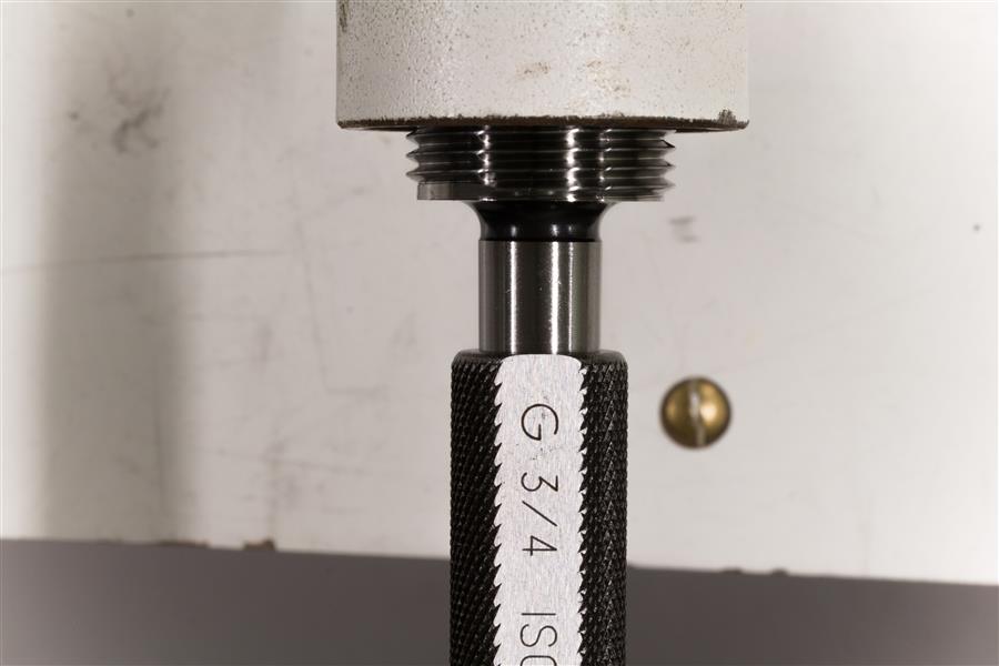
Before the publication of the NEN EN 144-1 in 1992, cylinders with a cylindrical thread BSPP ¾” (British Standard Pipe Parallel) were also widely used in the Netherlands. This cylindrical thread is often referred to as gas thread and marked with the letter G. Such a BSPP thread is therefore more commonly known as G ¾”. A corresponding BSPP ¾” tap therefore fits perfectly in such a cylinder.
In addition to the cylindrical thread BSPP ¾”, a conical thread W28.8 x 14 TPI according to DIN 477 angle 3:25 was also used in the Netherlands. This thread is better known in diving circles as ‘large conical’.
This large conical thread in a diving cylinder has not often led to accidents due to confusion with other screw threads. This is because a cylindrical threaded valve does not fit into the conical thread of the cylinder. However, when using a conical threaded valve in an aluminium cylinder, the cylinder thread could split or the velve neck would be damaged by too much tightening torque. For this reason, among others, the use of a cylindrical thread with o-ring seal was introduced.
In France, cylinders and valves were produced in the SI system (French: Système international d’unités) in the 1980s. This SI system differs from the metric system. France later adopted the metric system. Valves in the SI system were marked 25 x 2 SI or 25 x 200 SI. In contrast, the new metric valves sold today are marked M 25 x 2 ISO.
In America, cylinders and valves were produced with the 3/4″ NPSM thread (National Pipe Straight Mechanical). Cylinders with NPSM thread also find their way to Europe. Like the 3/4″BSPP this thread is a fraction larger than the M25x2.
The accidents that have occurred are due to the use of the wrong cylinder and valve combination. Some valves and cylinders are unclear or unmarked and can lead to incorrect combinations. In practice, these errors occur because cylinders and valves are bought separately. Combinations of old and new products also lead to these accidents. Divers travel a lot and often buy their materials all over the world. Purchases are made worldwide via the internet, and there is a lively trade on auction websites and sales sites, such as Marktplaats and eBay in the Netherlands.
These ingredients result in valves and cylinders seemingly forming a good combination. Because many amateur divers are unaware of the dangers of an incorrect fit, valves are sometimes screwed into cylinders with heavy tools. The thread is damaged and form an insecure connection. In practice, when the cylinder is brought to pressure, at around 150-180 bar, the force of the gas on the underside of the cylinder blows the valve violently out of the cylinder.
[intermezzo]
When the cylinder is filled with compressed air, this is usually done up to a pressure of 230 bar. After filling, the cylinder cools down and usually a pressure of around 210 bar remains available at room temperature. The final pressure depends on the filling speed and the room temperature and is determined by Boyle’s and Gay-Lussac’s law. We noted that, in practice, if the wrong thread combination was used, the valve thread often failed between 150 bar and 180 bar. To get an idea of the force with which the gas presses on the valve, we can apply the following calculation:
The contact surface of the male threaded portion of the valve, the ‘male stem’ with the gas is determined by the flank diameter d2 of the male stem’s wire diameter (see fig. 2). To calculate this, we take the cross section d – 0.65p. Here d = 25mm, and pitch p = 2mm. The flank diameter is then 23.7 mm. The area of the contact surface is therefore 4.4 cm2.
At 180 bar pressure, a force of 1800 N will be exerted on each cm2. The total force with which the gas will press on the valve would therefore theoretically be 4.4cm2 x 1800N = approximately 800 kg. An enormous force on this valve. If the valve fails, it will be a life-threatening projectile and the gas will be released explosively.
The table below describes most of the threads used in recent years in diving cylinders:
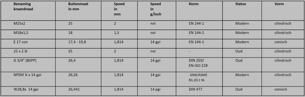
Tabel 1 External dimensions of valves Name,Outside diam, pitch, pitch in tpi (threads per inch), norm, status, shape
As tables like the one above do not provide enough information to determine the correct thread in the cylinder, more information is needed.
How do we determine the correct thread in the divingcylinder?
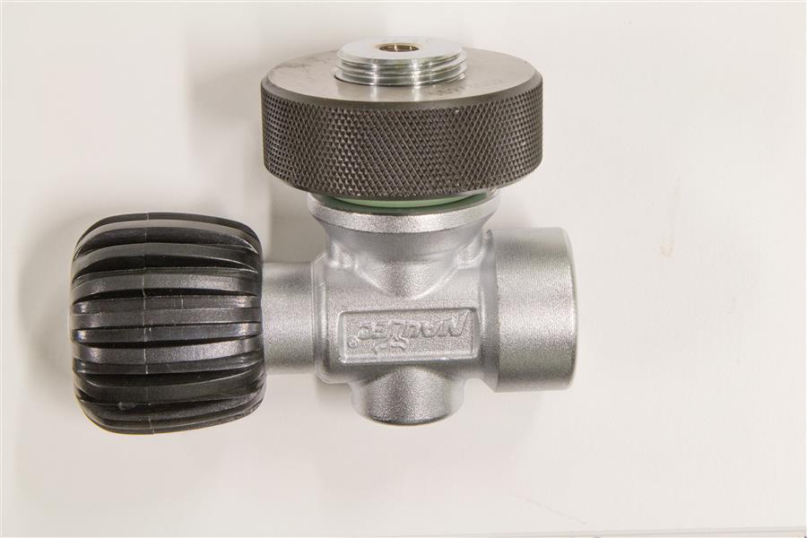
To determine whether we are dealing with a metric M25x2 valve or with a ¾” BSPP valve, we can easily measure the external diameter of the valve thread with a caliper. The M25x2 valve measures 25 mm and the BSPP ¾” valve measures 26.4 mm. It is a different matter to determine the correct thread in the cylinder. If we measure in a cylinder with an M25x2 thread, the dimension read on a caliper is not 25 mm. To determine which thread we are dealing with, we use a thread standard. Figure 2 shows a drawing of the metric thread. Here we see that the correct measure in the diving cylinder is called d’1 and is determined by reducing the outside diameter of the screw (d = 25 mm) by 1.08 times the pitch. This is 25 – (1.08×2.0mm) = 22.84 mm. If we measure 22.84 mm in the bottle, it may be M25x2 but we have yet to determine the pitch with certainty.
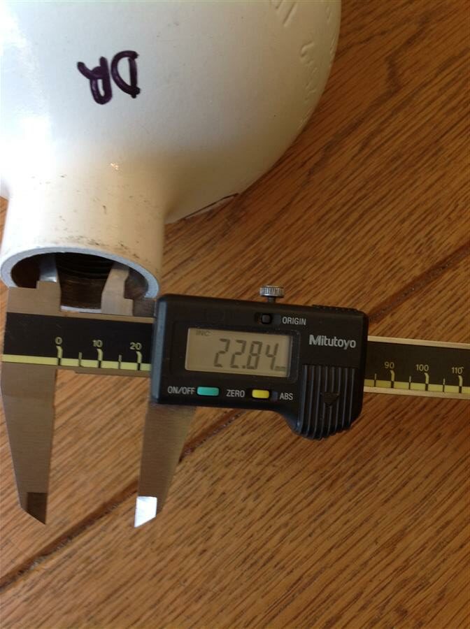
Afb. 1 The internal size of an M25x2 cylinder
Measuring the pitch.
We measure the pitch with a thread gauge. Such a meter can be bought for less than ten euros. If the thread comb 2.0 fits in the thread, we are dealing with a pitch of 2.0 mm.
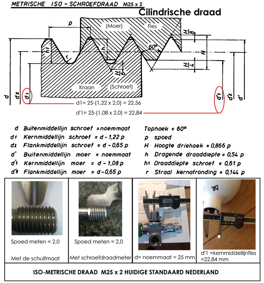
Afb. 2 Norm sheet isometric thread
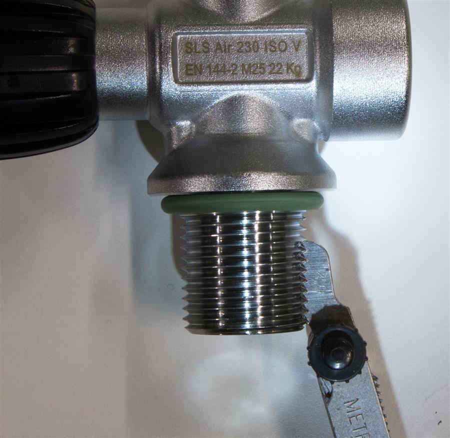
Afb. 3 Thread gauge on the valve
The fit of the valve in the cylinder is thus a very precisely determined ratio between pitch and angle. The tapered threads of the past and the G ¾” gas thread have a top angle of 55°. The top angle of the M25x2 thread is 60°. The pitch for M25x2 is 2 mm. This means that with each revolution the thread has increased 2 mm in axial direction. The pitch of the cylindrical old ¾” thread is 1.81 mm, and this is shown on the comb as 14TPI (14 threads per inch). The core diameter of the cylinder thread of the cylindrical BSPP ¾” cylinder is 24.64.
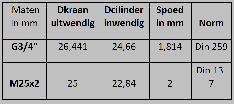
Tabel 2 Common sizes of the valve, Sizename, Dvalve_outside, Dcylinder_inside, Pitch, Norm
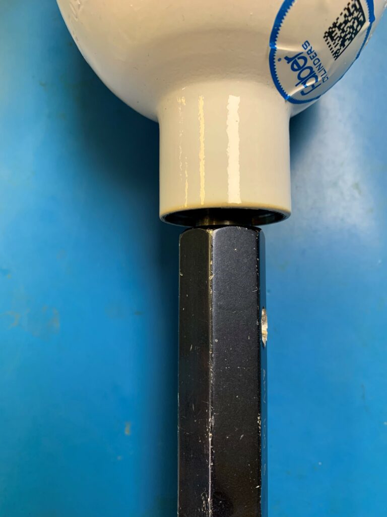
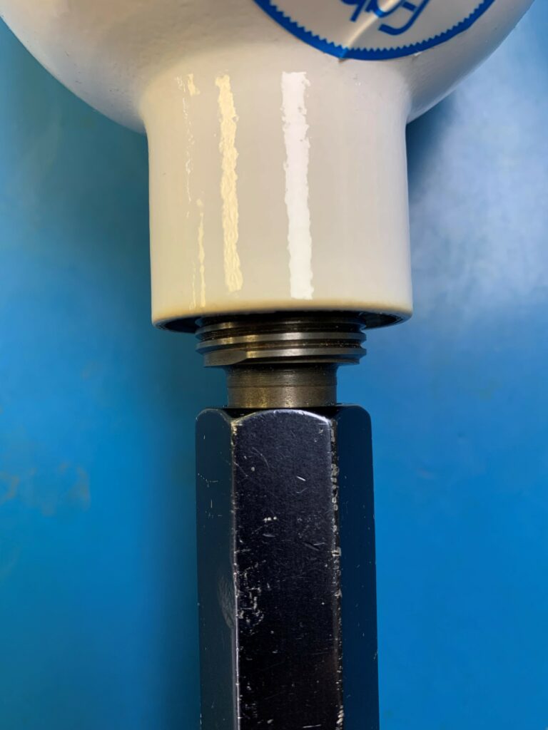
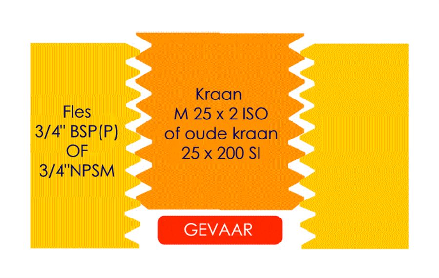
Some of the accidents have occurred because a new M25x2 valve was screwed into an (old) cylinder with 3/4″ BSPP. The valve will only develop resistance after 6-8 passes (revolutions), which makes the mechanic think that the valve is mounted correctly. A large spanner or spanner is used to further tighten the valve. As soon as the valve seals on the rim after the last two or three revolutions, the idea exists that the valve has been mounted correctly. Nothing could be further from the truth….
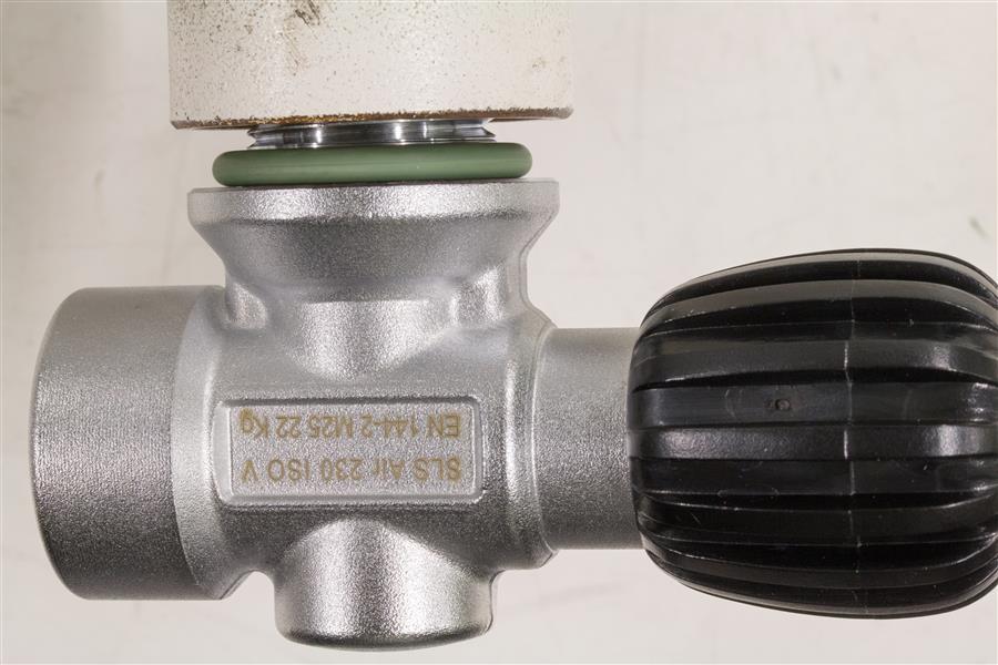
Afb. 4 Danger to life, an M25x2 valve in a G 3/4″ bottle goes in almost all the way….
How to exclude tolerance errors?
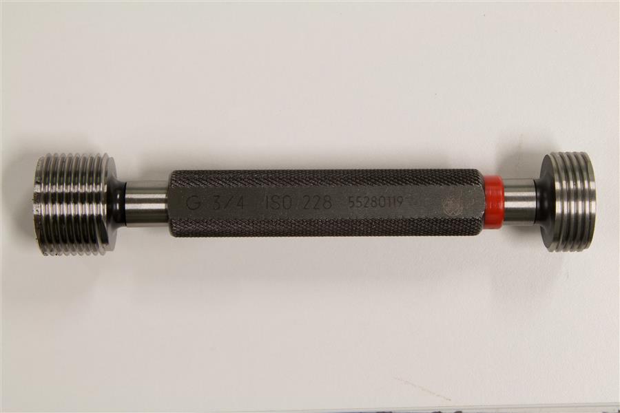
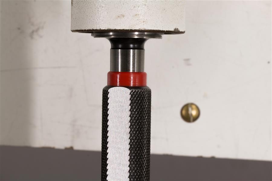
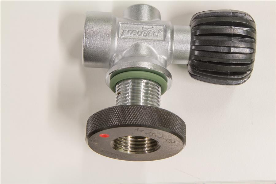
If a new tap is to be placed on a cylinder, the thread of both parts must be known. It must also be established whether the thread is within the wear and tear tolerances. This applies to the cylinder thread and to the valve thread. Go/No-go thread gauges are available on the market for this purpose. These relatively cheap thread gauges determine whether the thread is still within safe tolerances. Every maintenance technician or dive shop must have such tools. The black side of the gauge is go-gauge and when screwed into the cylinder with the black side the calibre must fit entirely into the thread (see figure 6). The red side of the gauge is the ‘no-go gauge’ and if the cilinder thread is within tolerance the no-go gauge will not srew in more than two turns.
If the red side of the calibre also fits completely into the cylinder, the thread is worn out and the cylinder must be condemned to prevent it being used!
Afb. 5 Approval / Rejection Go/No-go gauge
Afb. 6 Calibre should fits completely in the cylinder, thread meets specifications (black side)
Afb. 7 No-go gauge Calibre gets stuck before the end, thread is within tolerance (red side)
In this picture the gauge is to deep in the bottle and the bottle should be condemned!
Such gauges are also available for the external thread on the valve and work on the same principle.
Afb. 8 G0-Ring gauge fits the tap completely, thread is in order
Afb. 9 No-go Ring gauge gets stuck, thread does meet tolerance
A good tip when trying to identify the cylinder valve thread is to compare the thread with that of the insert. An insert is screwed into almost every valve outlet with a hexagon (behind the green o-ring) enabling the valve to be used for both DIN and INT regulator connections. This insert is screwed into the valve and always has a 5/8″BSPP thread which usefully has the same pitch as the BSPP 3/4″valve. When the insert is pressed onto the thread it is immediately clear whether we are dealing with a metric 2 mm pitch or a 1.814mm imperial pitch as the insert has a pitch of 1.814 mm.
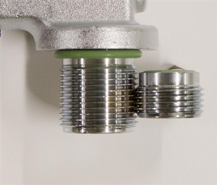
Afb. 10 Trick to quickly determine the pitch without tools, insert has same pitch as ¾ ” BSPP tap and fits perfectly
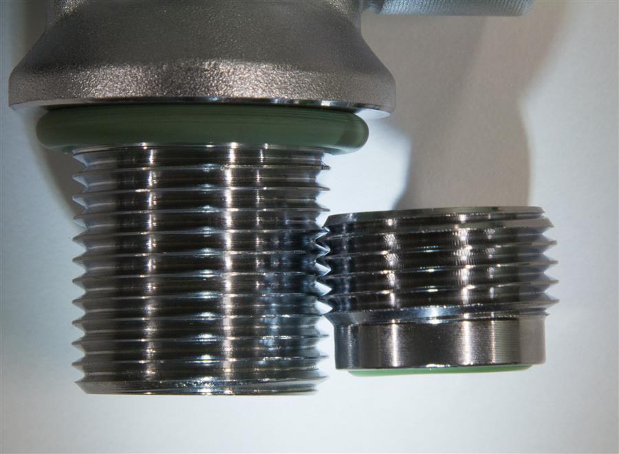
Afbeelding 11. Insert next to valve with thread other than G 3/4 “BSPP
If the thread does not connect properly (see fig. 11), we see a jump in the thread pitch and we may be dealing with a M25x2 valve. We can also use a valve with known M25x2 thread or an ordinary M16 bolt (M16 x 2 = the usual M16 size) to compare the pitch of the valve’s male stem.
Correct sealing
Cylindrical threads have no sealing function. An o-ring is used for this.
The valve, if correctly selected, must therefore be able to be rotated completely in the cylinder until the O-ring is pressed into the appropriate groove. This creates a static seal. The O-ring groove must correspond to the correct male stem.
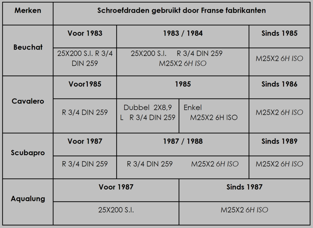
Tabel 3 Screw threads used by French manufacturers
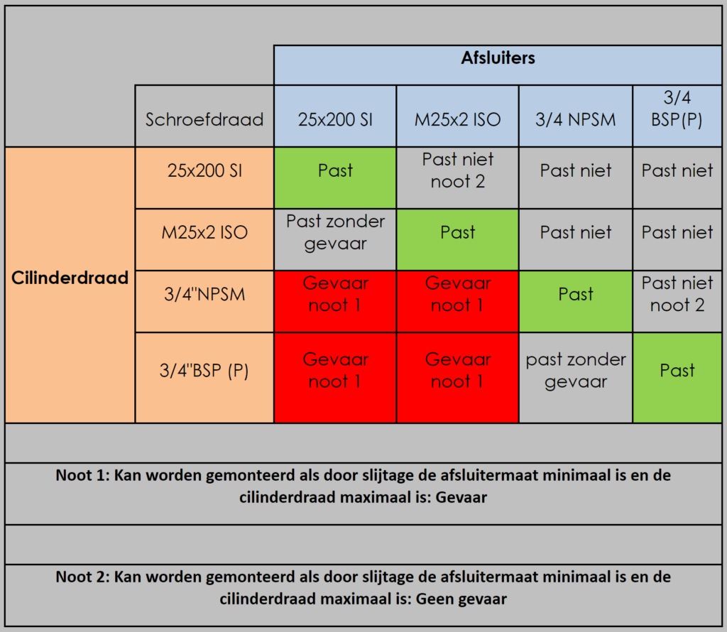
Tabel 4. Compatibility and incompatibility of threads for diving cylinders gevaar=danger; past zonder gevaar = fits without danger, past = correct conncetion, past niet = does not fit.
Conclusion:
Most valve accidents occur due to incompetent use. Valves and cylinders may be sold separately. As a result, amateurs without any knowledge of the subject place valves in cylinders that do not belong together. This can lead to life-threatening situations, including two deaths and several injuries in 2013 in Holland. Dangerous situations also arise for divers when the wrong valve seal causes the o-ring to fail. The breathing gas could escape from the cylinder and the diver could end up in an emergency situation. Finally, the use of compressed air valves with oxygen-enriched breathing mixes poses an increased risk of an internal oxygen fire in the valve. Therefore, the following recommendations are intended to prevent further accidents:
· Have the valve and bottle pair checked by a trained specialist only!
· Check that your cylinder and valve are correctly threaded
· Check that the thread of your valve is not worn out or damaged
· If your valve or cylinder does not display thread information drain the cylinder and have an inspection of the thread carried out.
· If you have a new valve installed in your cylinder, make sure that the threads belong together and are marked on the cylinder and the valve.
· If a valve and cylinder were mounted with the wrong thread, it is imperative to destroy both the cylinder and the valve as the thread strength will be affected.
· Check the O-ring fit against the figures shown to ensure correct fit. If in doubt, always consult a specialist.
· When diving with enriched mixtures, the valve must be suitable for oxygen or oxygen mixtures. This must be indicated on the valve.
The story below was originally published in the Belgian diving organisation Nelos’ magazine Hippocampus and is used with their permission in this article.
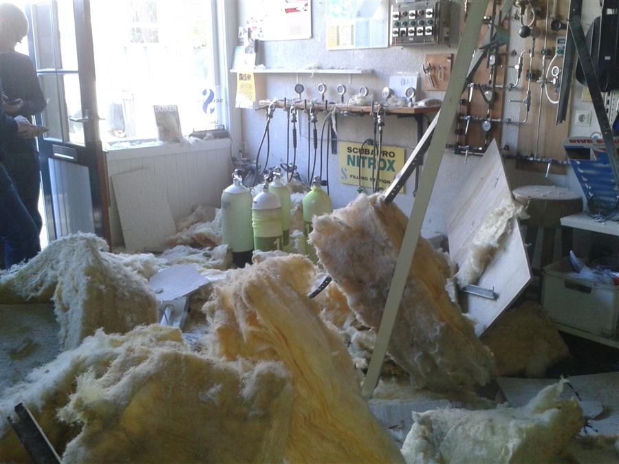
Figuur 13 The havoc after the explosion
On Monday morning, 7 October 2013, I was offered 4 diving cylinders to be filled. The knob of one of them was broken and I was asked to replace it. Meanwhile, the cylinders were filled to 200 bar.
Just when I was about to close the bottle with the faulty knob, it happened. With a huge bang, the valve of the bottle exploded.
You blink your eyes for a moment and then see the enormous havoc around you. The ceiling lies on the floor in a tangle of insulation material and other things. Through the open door, the cloud of dust moves away and slowly the realisation returns. I come to the conclusion that nothing physically has been hurt, only that I am slightly deaf in one ear because of the blast wave. The customers who are standing a little further away are fortunately not hurt, only extremely shocked.
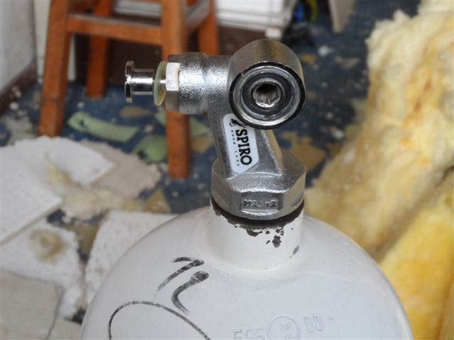
Figuur 14 The bottle with 3/4″ thread and M25x2 tap
How lucky we are, especially when I remember that in the last Onderwatersport of October 2013 (magazine of the Dutch Underwater Sport Association NOB) there is an article about a fatal accident while filling a diving cylinder on 16 August in Havelte.
The bottle is upright and the tap is next to it and is still attached to the filling hose, which has been lengthened by about 30 cm. This immediately shows the cause. It appears that the bottle, with the retesting in March 2013, is provided with a thread ¾” G while the tap has a thread M25x2. G while the tap has M25x2 thread. This of course does not fit well together and therefore a time bomb went off.

Therebreathersite was founded by Jan Willem Bech in 1999. After a diving career of many years, he decided to start technical diving in 1999. He immediately noticed that at that time there was almost no website that contained the history of closed breathing systems. The start for the website led to a huge collection that offered about 1,300 pages of information until 2019. In 2019, a fresh start was made with the website now freely available online for everyone. Therebreathersite is a source of information for divers, researchers, technicians and students. I hope you enjoy browsing the content!