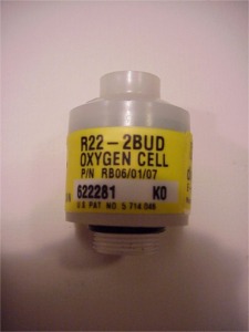
In 2001, we had problems with the Teledyne R22-2BUD oxygen cells. By switching the connection of two cells, it is easy to determine whether the cell is the cause of an alarm, or whether the problem is between the Master controller and the cell or the Slave controller and the cell.
So it was easy for us to establish that the cell was causing the problem. However, the difficulty was to demonstrate and prove that the problem was caused by the cell. The cell’s output voltage in air and oxygen were generally quite normal. Moreover, the response time of the cell to changing partial pressures was also completely normal. This made it extra difficult to prove that the problems were caused by the cell. By now exposing the cell to rapid changes in ambient pressure, and using the help of John Lamb of the Vandagraph company, we were able to prove to Teledyne, partly through video images, that the problem was caused by the cell. It resulted in an admission from Teledyne that there appeared to be a series of cells where the holes to equalise the pressure in the cell had been blocked.
The circuit board in the oxygen cell is coated in the case of the type R22-2BUD (like other Teledyne variants). The purpose of this coating is to give the components limited waterproof properties in case the scrubber runs full of water. Some of the shipped cells have an excessive amount of coating on the PCB which has the effect of clogging the holes for pressure equalisation.
These holes are meant to equalise pressure and are important for the cell’s response time. If the cell is exposed to front and rear pressure differences, the cell tends to overreact to these pressure differences. When using the Inspiration, this results in “Cell Warnings/and Errors” appearing on the display. Generally, these warnings are temporary in nature, but can sometimes persist for long periods of time.
Testing the cells by exposure to air and oxygen did not reveal these problems because they occurred at atmospheric pressure. Only variable ambient pressure revealed these problems.
This page shows YOU how to check the cells.
(Part of text as sent by Martin Parker of APD to all Inspiration owners on 26-03-2002)
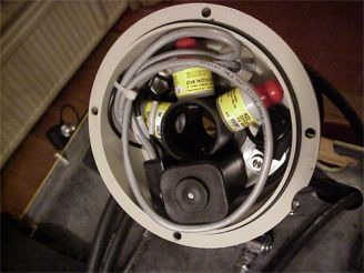
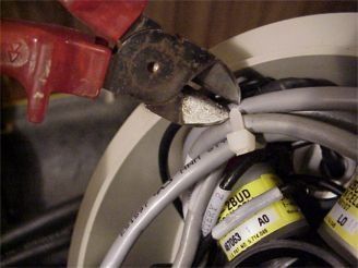
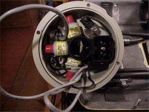
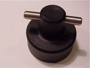
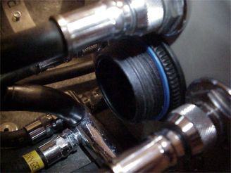
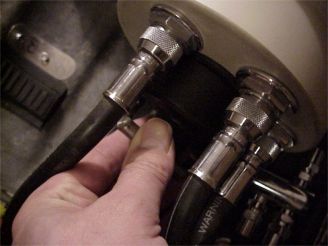
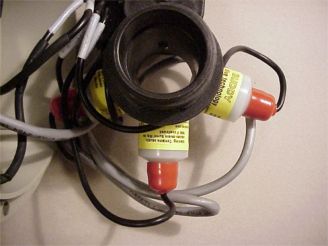
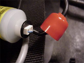
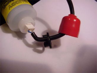
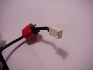
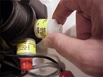
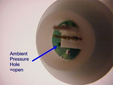
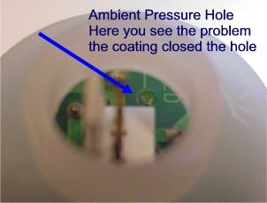
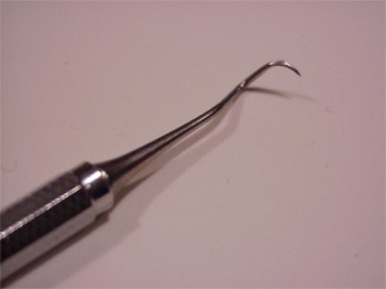
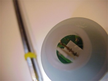
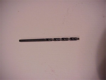
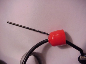
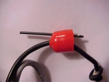
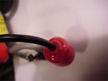
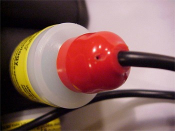
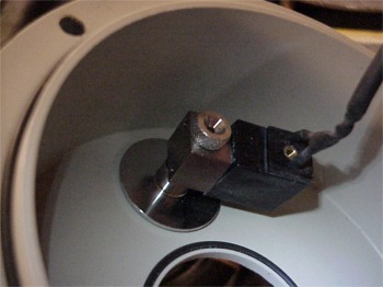
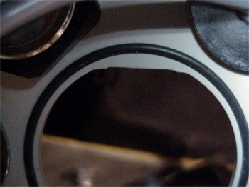
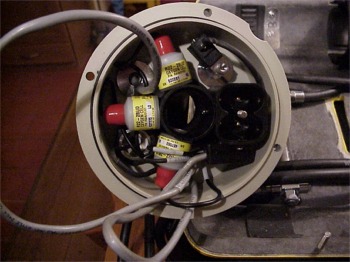
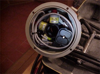
Here the inside of the scrubber lid. If you want to know the cell numbers you could take a short look at: . What we want to do is to check the cells on closed pressure balancing holes (PBH) and to make a small 2 mm hole in the red caps. The purpose of the holes is to be sure the pressure is equalised on both sides of the circuit board.First of all we have to prepare the inside by making access to the cells. I preferred to cut the Ty-rap for maximum space.Now there is a better view in the lid. I took out the batteries for safety reasons. When the wiring is manipulated I think it is better to have no current.we need the nice standard equipment delivered with the inspiration, to unscrew the nut on the top of the scrubber lid.Here it is, take care that you place the tool very tight to the ring to prevent damage. You do not need to block the cell holder on the inside.turn left for unlocking the ring. (CCW)Now you can gently take out the cell holder and see the components. Gently pull the red cap from the cellNow pull the black connector lockAnd finally pull the white connector from the cellNow you can unscrew the cell by tuning left (CCW)Check your cell on type and serial number and write it in your logbook. THIS is the moment to start your cell registration!Here is the cell shown on the connector site. The blue arrow points to the pressure hole. As you see this one is open and fine.Here you see the same cell, but on the other site. Here you see the problem, the hole is closed with the coating. As Martin wrote it could only cause a problem with both holes closed, I prefer both holes opened so I decided to arrange this.I have a very nice tool, a present from my dentist. This tool is very capable to punch the small hole and solve the problem. APD advised to sent the cells back when both holes were closed, but in my case only one hole was. If both holes are filled with the coating I would choose to sent them back.Here you see the cell with the punched hole.Now we have to make a hole in the red caps to let the air equalize.Here a warning is at his place. Take great caution to not damage the wire to the cell. I bend the wire away from the 2 mm drill, so if it would punch through with force, it would not damage the isolation.doneHere you see the result. Be sure the hole is clean and you should be able to see through.OK, now replace the cell and the red cap, and repeat these steps for cell 2 and cell 3.Before replacing the cell holder check the solenoid wiring and take care that the wire is in parallel direction of the gas addition.Here you see a detail of the inside of the scrubber lid. Before replacing the cell holder, be sure that the O-ring is in place. Also here is seen that the cell holder will only fit in one way because a quadrant of the fitting is edged.Now gently replace the cell holder. Let the wiring point outside the unit. Gently turn the cell holder till it snaps into position. Now replace the locking ring. Don’t forget the blue indicator.Finishing this check, you rearrange the cabling and punt a new Ty-rap®. Replace the batteries and check functionality.
Therebreathersite was founded by Jan Willem Bech in 1999. After a diving career of many years, he decided to start technical diving in 1999. He immediately noticed that at that time there was almost no website that contained the history of closed breathing systems. The start for the website led to a huge collection that offered about 1,300 pages of information until 2019. In 2019, a fresh start was made with the website now freely available online for everyone. Therebreathersite is a source of information for divers, researchers, technicians and students. I hope you enjoy browsing the content!