
This comprehensive article describes the development of oxygen diving equipment for military applications. I was allowed to publish the article written by Helmut Knüfermann on my website with his highly appreciated permission. The article gives an able insight into the development steps from the first beginnings to today’s advanced diving apparatus.
Chronological development of closed-circuit oxygen scuba diving equipment from the Dräger factory for military use
By Helmut Knüfermann
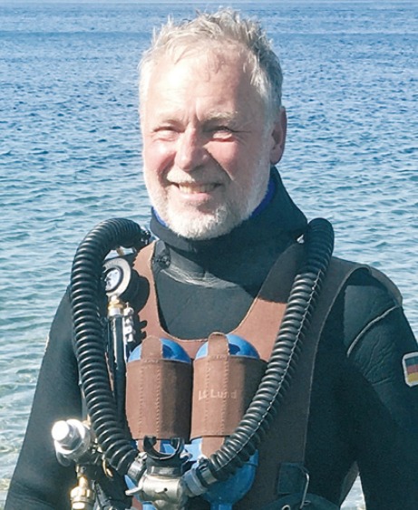
Our Author Helmut Knüfermann, born in 1944, was a swimming-diver (Schwimmtaucher) for the German Navy. After completing his physics studies, he worked for 34 years in research, development, and sales of medical implants. Helmut has been diving since 1958 (since 1969 with the Dräger “Lieutenant Lund II”) and, after his retirement, is involved with the history of Dräger oxygen rebreathers for military use, which he collects and still uses today.
In this article that consists of 4 parts describing a large number of oxygen rebreathers. To this end, a compact index is available. The article consists of 4 parts and there is a separate index for the types of diving apparatus.
part 1
Part 1: Kleintauchgerät 138, Kampfswimmergerät, Schwimmtauchgerät, Badetauchretter, Baderetter, Gegenlunge TR and Tauchretter
Part 2: Kleintauchgrät 138, Leutnant Lund I, Kleintauchgrät 138L, Leutnant Lund II, Norge I, Norge II, Modell 600
Part 3: LAR0, LAR I, Lar II, Lar IIa, Kar I, Lar IIc, Lar III
Part 4: Lar IV, Lar V, Katox
s1
s2
s3
s4
PART 1
Devices in “Vest” design up to and including “Dräger small diving apparatus 138”
This article is intended to provide an insight into the designs and constructions of the military oxygen rebreathers manufactured by Drägerwerke up to and including the “LAR V” device type. Later devices are not included. I have deliberately omitted the complex subject of diving physiology and diving medicine for diving with pure oxygen as a breathing gas, with the exception of a few details that are useful for understanding the functions of the equipment.
Descriptions of military strategies and operations are also not included, as only the special technical features of the diving equipment manufactured for this purpose are to be described here.
Parts 1 and 2 (in the following issue) of this article describe the history and, in the further course, the type chronology of the early devices in “Vest” design, made of rubberised textile fabric. The “hard-shell” devices made of glass fibre-reinforced polyester resin, which were manufactured at a later date and worn on the chest, are the subject of Part 3.
Sea fighter with reed snorkel
The trick of surprising opponents from the protective cover of the water is as old as mankind itself.

Stories of Indians who breathed underwater through reeds in order to overpower their unprepared tribal opponents have fascinated me since my youth.
The first known records of underwater sabotage from Herodotus, 450 BC, refer to information from the Spartan military leader Pausanias about Scyllias and his daughter Hydna (Cyana), who cut the anchor ropes of Persian ships off the Greek coast with their sabotage [Picture 1]. The ancient Greek legend tells of “θάλασσα μαχητής”, meaning “sea fighters”.
Related terms can be found throughout ancient mythology, in which warlike actions under water are reported. In his epic about the Roman civil war between Caesar and Pompey, the Roman writer Lucan, 39 – 65 AD, wrote of the “mare pugnator” – “sea-rider”, which was passed down in later literature as “sea-fighter”. This lyrical transformation of the official term “swimming diver” was also used by the German Navy during the Second World War.
It was not until the invention of portable diving equipment in the 20th century, whose closed circuit did not allow any treacherous air bubbles to reach the surface, that it became possible to stay underwater for longer periods of time without a “reed snorkel”. This was of course of great military interest. It is therefore not surprising that the development of these devices was heavily subsidized by military impulses and funds. Many nations, particularly the Italians and the British, repeatedly designed new and better rebreathers, whose use caused a sensation, especially during the last world war. It was only natural that a German manufacturer with a long track record in the production of oxygen rebreathers for use above water should use its expertise to produce rebreathers for combat swimmers: the “Drägerwerke” in Lübeck.
History of closed oxygen breathing apparatus
Without the history of the oxygen breathing apparatus developed by Drägerwerke, this article would hardly be conceivable. Over the course of 70 years, the experience of the leading engineers Hermann Stelzner, Hermann Tietze and Gerhard Haux led, among other things, to the production of closed-circuit oxygen breathing apparatus for combat swimmers.
The first inventions of a portable closed oxygen breathing apparatus based on the principle of
generation with binding of the exhaled carbon dioxide by a chemically active substance date back to the middle of the middle of the 18th century. These devices were initially used in mining and rescue operations, where contaminated or contaminated or poisoned ambient air was to be expected. was to be expected. It was not until the Englishman Henry Albert Fleuss (1851-1933), originally a ship’s officer in the merchant navy, constructed designed an oxygen breathing apparatus that was also suitable for use for underwater use and was produced from 1879 in the factory for diving equipment. by August Siebe in London from 1879
The diving engineer at Siebe & Gorman, Robert Davis (1870- 1965), developed the rebreather together with Fleuss in 1903 into a diving rescuer. Thus, in 1903, the oxygen rebreather into the legendary “Davis diving rescuer”(DSEA) at the same time, Drägerwerke in Germany was working on oxygen rebreathers based on the same principle – initially for use by fire brigades and in mines. “The start of development of German diving rescuers based on oxygen circulation can be dated quite precisely to the year 1910” [EN 1]. Hermann Stelzner (1884-1942), engineer at Drägerwerke since 1906 and later chief engineer, designed the “Dräger- Submarine Diving Rescuer DM1”, as well as the “Dräger Diving Rescuer D2”. In the years that followed, he designed a series of further oxygen breathing apparatus for various applications above and under water. In 1915, for example, he developed the “bathing diver’s rescuer”, in 1928, the “counterlung”, from 1940 the “Dräger- small diving apparatus” and in the 1940s a new lightweight “Dräger diving rescuer”.
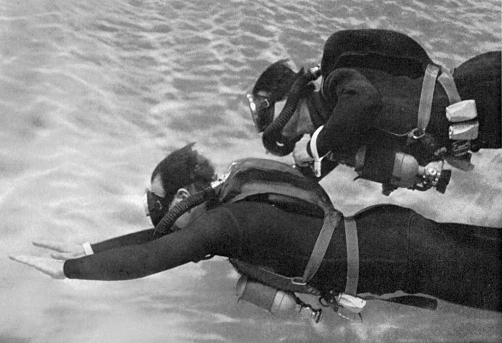
These small and lightweight constructions paved the way for autonomous Dräger diving equipment, which, in combination with flippers, allowed for extraordinary underwater mobility, in stark contrast to the previously used helmet diving equipment, which, due to its weight, could only be used within a limited radius from the deployment site.
None other than Hans Hass (1919-2013), an Austrian zoologist and marine researcher, significantly contributed to designing the first German small diving device. Together with Hermann Stelzner, he constructed in the spring of 1941 a new type of diving equipment from the “Dräger counter-lung” (see “Aegean 1942” in TH2 2014 by M. Müller), which he used from 1942 for over a decade in several exemplars for his expeditions, and later received the designation “Dräger 138 small diving device.”
The limited production of this small diving device suggests that this, like other Dräger devices, was used by the “sea fighters” of the German Navy at that time. However, no proving documents or indications for this are available to date. According to research, only “Dräger diving rescuers” and the “Dräger small diving device” from 1940 were tested for combat swimmer missions. The short duration of use of the devices was insufficient for these purposes. It is further reported that Alfred von Wurzian, an expedition companion of Hans Hass, also conducted experiments for a corresponding combat swimmer diving device in collaboration with Dräger. It is documented that submarine crews of the small combat units were equipped with Dräger submarine rescuers.
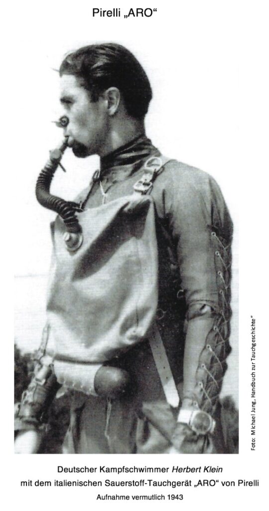
Since the combat swimmers of the Kriegsmarine received their training from the allied Italian “Gamma combat divers” at the training centre “Kloster San Giorgio on Alga in the Venice Lagoon” from the end of 1943, they were equipped with Italian Pirelli small diving devices (pendulum respirators)[Picture 8] from [EN2].
It was not until the end of the war that the German naval command recognized the value of combat swimmer missions. However, an increasing shortage of materials – even in the Dräger diving rescuer production – prevented the serial production of combat swimmer diving devices.
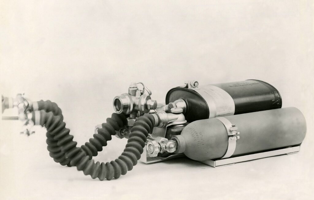
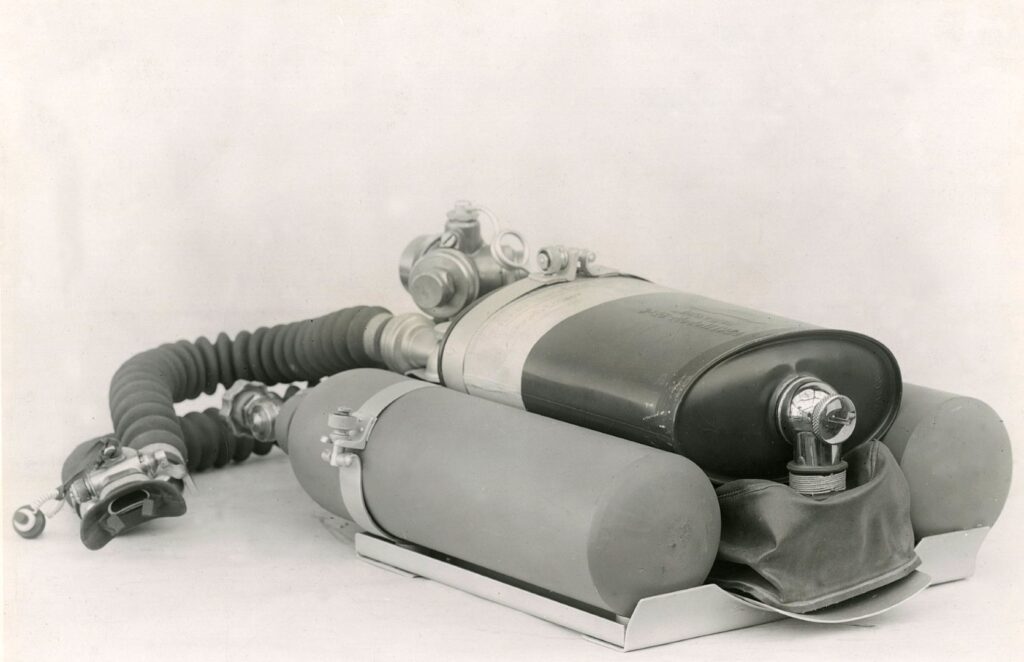
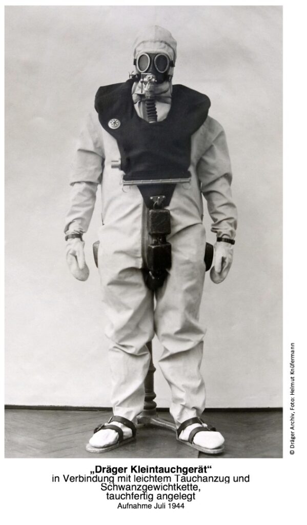
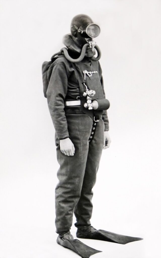
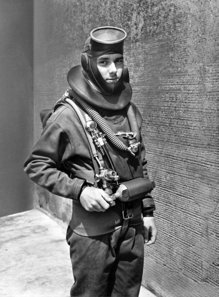
Nevertheless, during the war, Drägerwerke already had a finished diving device with a closed oxygen cycle “in the drawer,” in which Herrmann Stelzner was probably still significantly involved in the construction. However, production could no longer be started in the final stages of the war. [Picture 2 and 3] Design plans and drawings have not been found to this day. In the summer of 1945, a special department of the British occupation troops confiscated documents and devices from Drägerwerke and transported them to England[EN 3].It is not out of the question that parts of this expropriation are still in English archives today. Many products were immediately banned from production at that time due to their potential military usability, including diving devices. It would take until the early 1950s for Drägerwerke to officially return to manufacturing. military oxygen rebreathers for combat swimmers
More on this in the next instalment of this article.
Civilian Dräger oxygen diving apparatus before 1945
The Dräger Baderetter and Badetauchretter [EN4]
In 1913, the Drägerwerk created the “Baderetter”, based on the “Tauchretter” was developed at the Dräger factory. This oxygen diving apparatus was intended for use in water rescue. Technical documents are no longer available, so it is so that it is unclear to what extent it differs from the diving rescuer. All that is known is that the buoyancy was to be regulated with an inflatable buoyancy bag. The device should also enable strenuous work. The diving time was limited to 45 minutes, or 30 minutes at greater depths, limited. Two years later, the “bathing diver rescuer” was designed at the Drägerwerk was designed. Technically, it was largely similar to the “Dive Rescuer D2” [EN 5]. It did not have an additional compressed air cylinder (like the “Tauchretter DM2”). In 1926, the Drägerwerk launched an improved version of the bathing diver rescuer, the “Model 1926”, onto the market. The diving properties of this model were to be enhanced by additional iron sandals and a heavy neck chain.
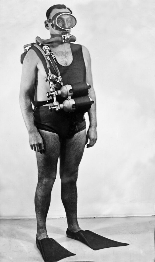
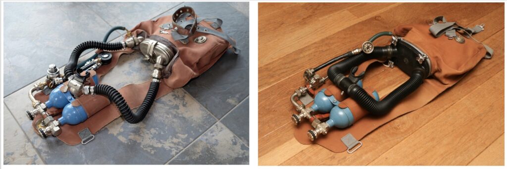
The “Dräger-Gegenlunge TR”, small diving rescuer for use down to a depth of 15 metres [Picture 4]
In contrast to the models in the DM series and the bathing rescue device the counterlung is a pendulum breather. This means that there were no separate breathing hoses for inspiration and expiration. The diver breathes in from the breathing bag through an alkaline cartridge and a short piece of hose and exhales in the same way. The counterlung was a closed breathing apparatus.
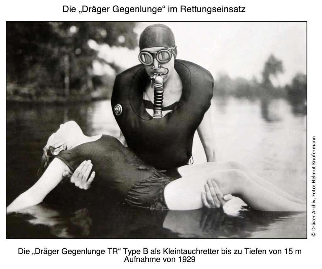
The oxygen was topped up manually from a cylinder, which was located in the breathing bag and could be operated from the outside. The bottle size was 0.4 litres, and the maximum filling pressure was 150 bar. This meant that approx. 60 litres of oxygen were available. Through the lower opening, which was closed by a clamp rail, the oxygen cylinder and the alkaline cartridge could be replaced. The breathing air that expanded as the diver ascended escaped through a valve on the right side of the chest of the of the device. Further equipment included diving goggles, a nose clip and various weights. The “Dräger counterlung” was described by the manufacturer in the operating instructions however, due to its limited capacity for light underwater work.
The “Dräger -Kleintauchgerät” for light diving work
The small diving apparatus [Fig. 5], also a pendulum breathing apparatus, was a further development of the ‘Gegenlunge’, intended for light underwater and also intended for water rescue. intended for water rescue. In a catalogue from 1933, this version of the counterlung version of the counterlung with a larger alkaline cartridge and a larger oxygen cylinder of 0.6 litres instead of 0.4 litres. The small diving apparatus was first advertised in 1940. The modified device is similar to the aforementioned form of the counterlung. Here, too, the oxygen was refilled manually from a bottle. Due to an enlarged alkaline cartridge and oxygen cylinder, the diving time was 35 minutes for light work or one hour at rest to a depth of 13 metres. The small diving device weighed without weight chain approx. 3.5 kg.
The “Dräger-Tauchretter” “submarine escape unit”, Mod. 1944
This diving rescuer [Figures 6 and 7] from the year of production 1944 also corresponded technically to the design principle of the counterlung and small diving apparatus described above. This pendulum breathing apparatus was used for exiting from sunken submarines down to a depth of 100 metres. The Breathing from the diving rescuer only took place shortly before the submersion, to avoid harmful oxygen exposure in the event of high air pressure exposure to oxygen. Chlorine gases in the boat….
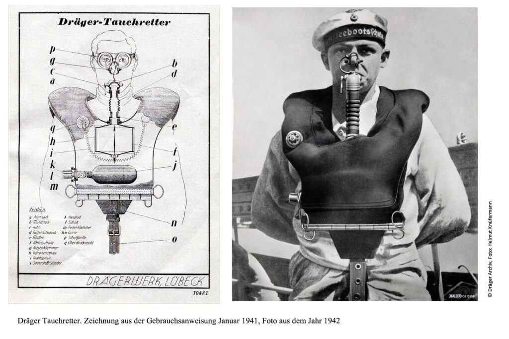
Image 7: Drawing from the instruction manual January 1941 © Dräger Archive, Photo: HK (left)
required immediate use. For surfacing from depths of 30 to 100 meters, the breathing bag should be filled with about three breaths of air and the rest with oxygen. During an unforeseen prolonged stay in the boat or a longer ascent, it was necessary to refill oxygen every 5 to 10 minutes. The alkali cartridge and oxygen supply were sufficient for about half an hour.
The expanding breathing gas in the breathing bag during the ascent escaped through the overpressure valve and should also be released at the corners of the mouth. This diving rescue device was also used as a water rescue device, gas protection device, and in emergencies as a breathing apparatus for firefighting.
Use and Construction of Military Oxygen Recycling Devices
During World War II, some nations with their combat diver special units had already proven that targeted acts of sabotage could thwart the enemy’s planning and execution.
Lieutenant Commander Herbert Völsch stated [EN 6 ]: “There are hardly more effective methods to weaken opponents unnoticed than the silent and bubble-free intervention by combat swimmers underwater. These methods differ with their cunning, camouflage, and surprise from the ‘classic open engagement’ through ‘asymmetric warfare’.”
“An advantage of ‘asymmetric warfare” lies in the ratio of low effort to effective benefit. Experience has shown that a combat swimmer team is capable of immobilizing a heavily armed military unit with simple means. “Tactical combat swimmer operations require the use of oxygen recycling diving devices that significantly differ from civilian versions and are specifically designed for this need:
– Silent operation
– Non-magnetic design
– Closed, bubble-free recycling principle
– Cold-resistant
– Blind handling capability, glove-friendly
– Quick donning and doffing of the device
– Uncomplicated technical structure
– Military robustness
– Reliable and quick readiness for use
– Smallest possible size for maximum duration of use
– Light weight
– Unobtrusive colouring
The combat swimmer devices from companies like Siebe & Gorman, Mommsen, Lambertsen, Dunlop, and Pirelli, among others, more or less fulfilled these characteristics during the world war. Most devices were worn with a breathing bag and oxygen bottle on the chest and were pendulum breathers (see [Image 8] “Pirelli ARO”). The oxygen supply was provided by manually opening the bottle valve. The mouthpiece had a simple shut-off valve, and the lime container was usually located in the breathing bag. There was no manometer to determine the bottle pressure (no more oxygen = surface) – simple constructions.
Generally familiar, but for a better understanding of the devices described below, the principle of closed oxygen circulation devices: The breathing system – Pendulum breathing system, in which a single breathing tube is used to inhaled and exhaled via a single breathing tube. After 1945, oxygen rebreathers for military use are increasingly by more advanced circulation systems replaced. – Circulation system with a real circuit. Inhalation and exhalation hose are separate, and the direction of the breathing gas flow is determined by control valves.
The oxygen supply
In principle, oxygen can be supplied to the respiratory circuit in three different ways:
– manual supply, no longer used for military devices (such as the Pirelli ARO from 1943 [Fig. 8])
– constant dosing, devices with continuously adjusted (usually 0.8 – 1.2 l/min) (all devices in parts 1 and 2 of this of part 1 and 2 of this article)
– automatic lung dosing, automatic lung devices, in which oxygen is automatically added as the volume of the breathing bag (type: LAR, all devices in devices in part 3 of this article) Both of the latter device types can be equipped with a manual add-on valve with which spontaneous administration of oxygen can be of additional oxygen is possible.
Dräger oxygen rebreathers for military operations after 1945
The “Dräger small diving apparatus 138” (Dräger drawing no.: T3200)
As described, Dräger already manufactured an oxygen small diving device for Hans Hass in 1942 [EN 7]. Together with chief engineer Hermann Stelzner, he designed a new small diving device from the “counter-lung” in 1941. The main changes involved relocating the carrying position of the breathing bag from the chest to the back, a continuous oxygen supply to the breathing bag with an additional oxygen dosing valve, and converting the pendulum breather into a closed-circuit rebreather, where inhalation and exhalation took place through two separate corrugated hoses.
Many trials, modifications, and patent applications were carried out until it was satisfactorily usable. A patent from the final war years included another improvement of the breathing bag, which was only recognized in 1951 due to the takeover of government authority by the Allies in 1945 and the associated consequences and barriers.
This oxygen closed-circuit device later received the designation “Dräger-Kleintauchgerät 138” and was officially marketed by Dräger from 1952. According to unverified information, Dräger delivered a few units to the “United States Navy” for military use even before 1951 [EN 8]. Devices for this application fell under the War Weapons Control Act at the time. It is likely that the Allies managed to bypass this in secrecy. The records have been destroyed.
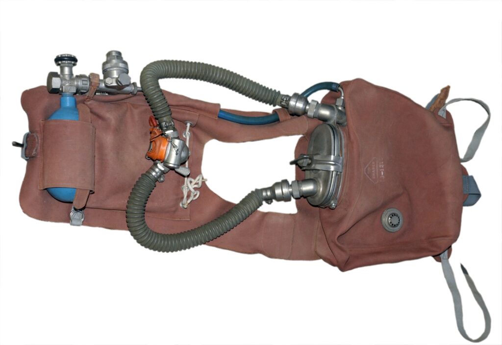
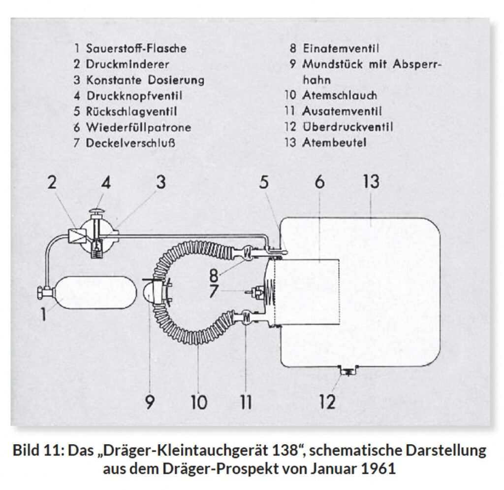
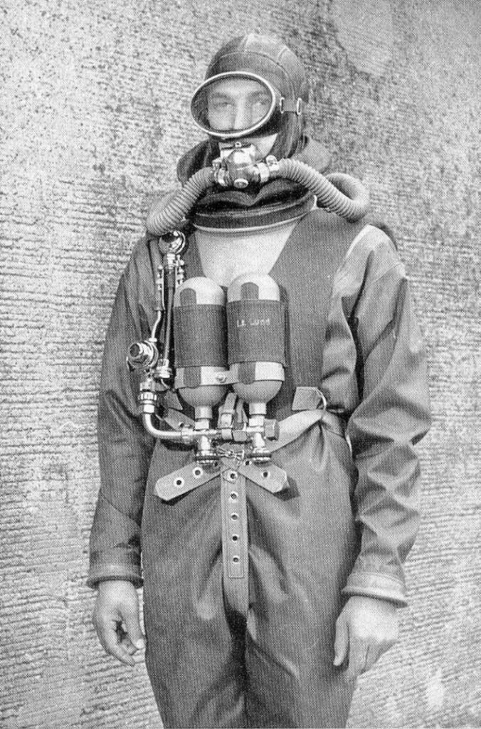
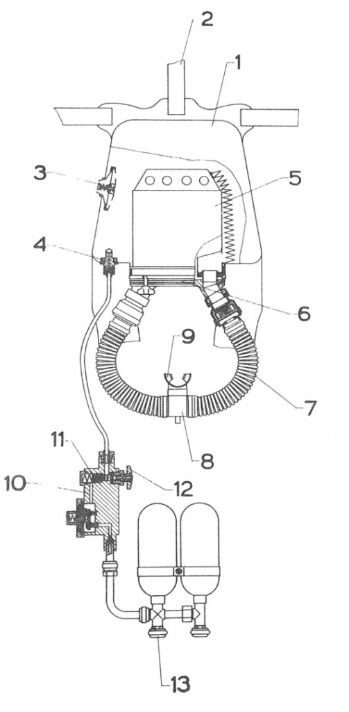
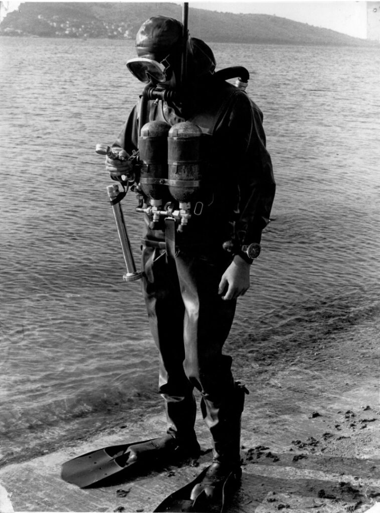
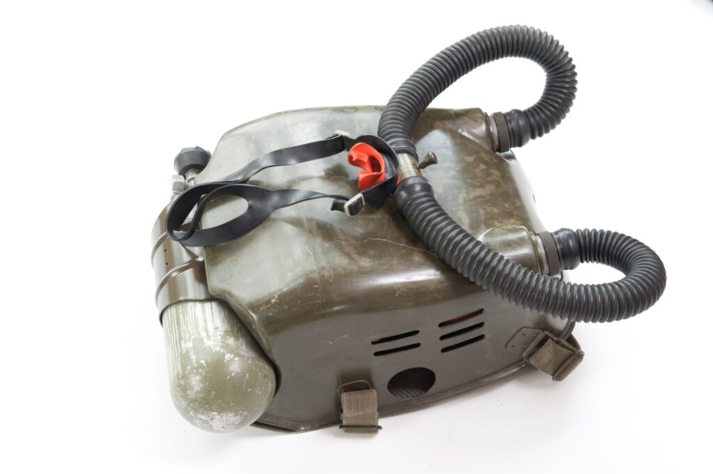
The technical construction of the “Dräger 138” was essentially completed in 1952. The back part of the vest, made of rubberized reddish-brown textile fabric, had an integrated breathing bag. The vest carried the 0.6-liter oxygen bottle with a filling pressure of 150 bar on the chest part. Additionally, there was a pocket on the chest part for additional lead weights for buoyancy control. Unlike pendulum breathers, inhalation and exhalation here took place through separate corrugated hoses with integrated valves. Thus, the breathing gas in the circuit travelled through the 1-liter soda lime refilling container and the approximately 7.5-liter breathing bag [Image 11].
The inhalation and exhalation valves were not directly at the mouthpiece but at the device-side hose connections. The mouthpiece [Image 29 Part 2] had a built-in shut-off valve to block the breathing circuit from ambient air when not in use. A loop on the mouthpiece held the nasal clip, whose use was mandatory at the time.
The operating manual G 221 from 1956 contained the following note, which could hardly be ignored even with effort: “If the breathing bag does not fill when pressing the oxygen add-on valve button, the oxygen supply is depleted. Then you must surface immediately.”
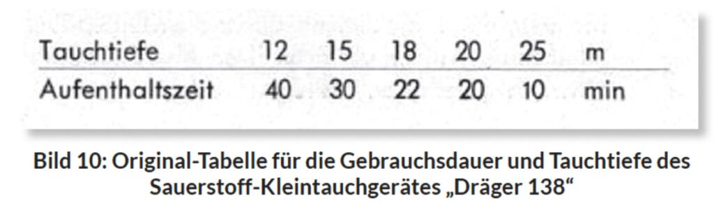
The standard version of the “Kleintauchgerätes Dräger 138” did not include a pressure gauge for checking cylinder pressure, which would have been desirable for more frequent and professional use of the device. So, it is not surprising it is therefore not surprising that Hans Hass was already was equipped with “Dräger 138” predecessors for his expeditions, which contained a pressure reducer with pressure gauge. The pressure regulator described in the Dräger instruction manual 65-G 11/G from 1952 (1st edition) for the “Dräger 138” were for the depth of use and dwell time referred to “low physical referred to “low physical work at an oxygen concentration of approx. 85 concentration in the breathing bag – after correct breathing and filling with pure oxygen”. Even if the instructions for use clearly point out the dangers of oxygen deficiency and oxygen poisoning, the usage data in the usage data in the Dräger table of the original instructions for use appear daring according to current knowledge [Fig. 10]. However, none other than Hans Hass himself, to whom the construction of this rebreather is due to no less a person than dived to depths of more than 25 metres.
Dräger continued to manufacture the “Dräger 138 small diving apparatus” until the mid-1950s and also marketed it as a recreational as a scuba diving device via the company “Barakuda” in Hamburg. The selling price at that time was DM 490. Even before 1951, the “138” was already being sold to various western naval units. Among others, the “United States Navy” for use in the Korean War (1950-1953) ordered a number of examples. Not through direct delivery, but via detours the “Dräger 138 small diving apparatus” also reached eastern.
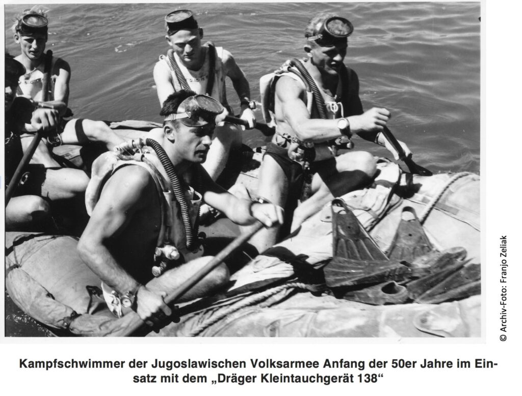
From 1948, the Yugoslav army received U.S. military aid until the 1950s. As a result, they had a mixture of originally Soviet, American, and increasingly self-produced weapons systems and equipment for decades. Some of the “Dräger small diving devices 138” purchased by the US Navy (UDT) in 1951 for use in the Korean War also found their way to the Yugoslav People’s Army through military aid [Image 13].
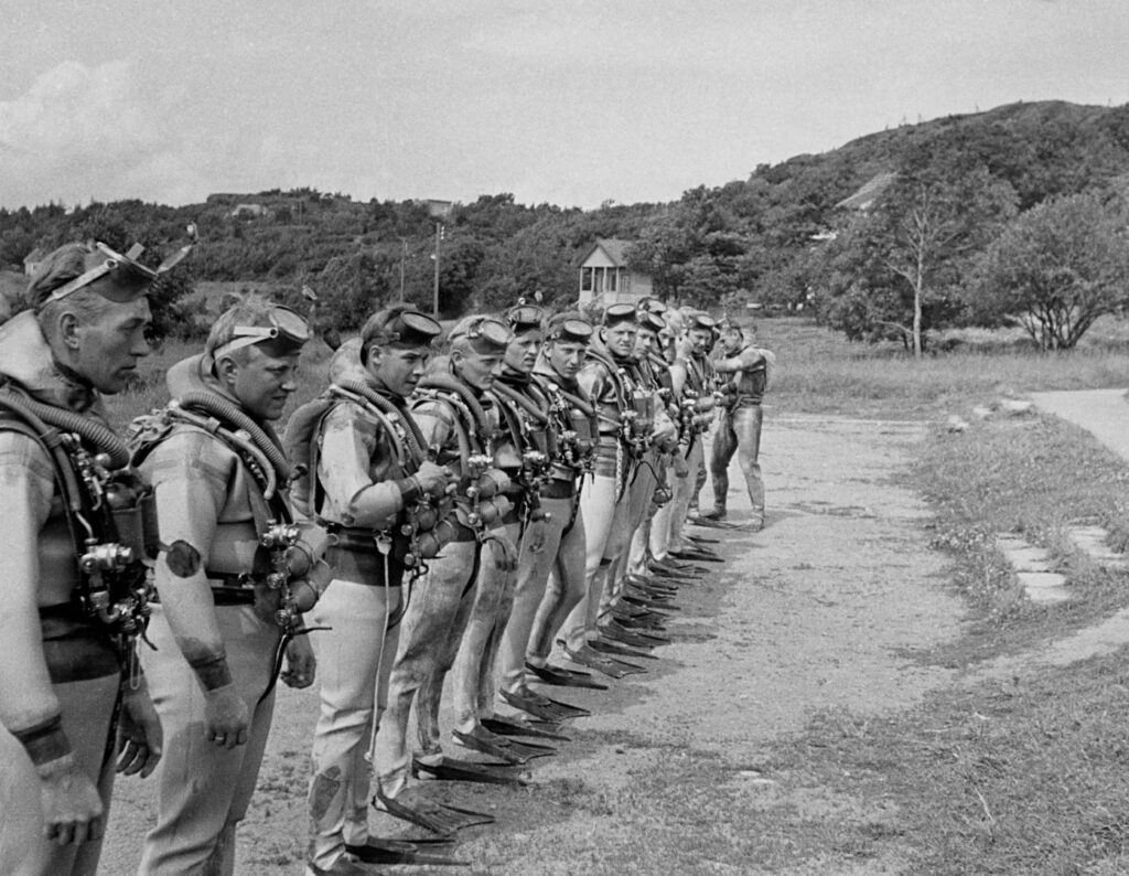
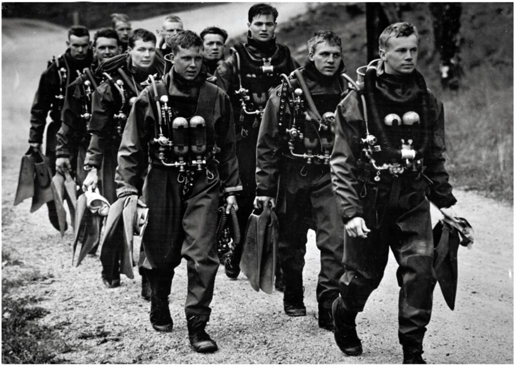
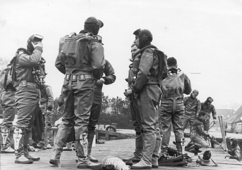
As a founding member of NATO in 1949, the Norwegian Navy had a particular interest in securing its coastlines and introducing special forces. The successes of Italian and English underwater saboteurs in World War II were the focus of the “E-Service” division of the “Sjøforvarets Overkommando” (Naval High Command). Thus, from July 1952 to May 1953, Ove Lund, a Norwegian naval officer, received “frogman training” at the “SOK / A III E.” (Navy Command) in the USA. He trained there with the “Dräger 138”.
In December 1952 (during his Christmas vacation at home), Lund met personally with Heinrich Dräger at the Dräger works in Lübeck [EN 9], bringing the concept of the “SOK E-Service” for planning a Norwegian Navy frogman school and the task of procuring the necessary equipment. Based on his experience with the Dräger closed-circuit device at the US Navy, the decision for a “Dräger device” was made for the “Dräger small diving device 138” [Image 12] was a natural choice. Initially, they agreed on a first delivery of a few devices. Although no records exist of the delivered quantities, the use of these devices at the start of the frogman school is documented in the graphical representation of the “SJØ-FORSVARETS DYKKER- OG FROSKEMANNSSKOLEN”.
In March 1953, Lund (by then “Lieutenant”) worked with the first instructors in Oslo, Ørnulf Theodorsen, and other trainers to develop a strategy according to his ideas. That same summer, the first test of Norwegian applicants took place on the Bolærne island group in the Oslofjord. 8 out of 24 applicants were selected. The students came from the navy and the coastal artillery. The frogman school used the newly delivered “Dräger 138 closed-circuit devices” during the course of 1953.
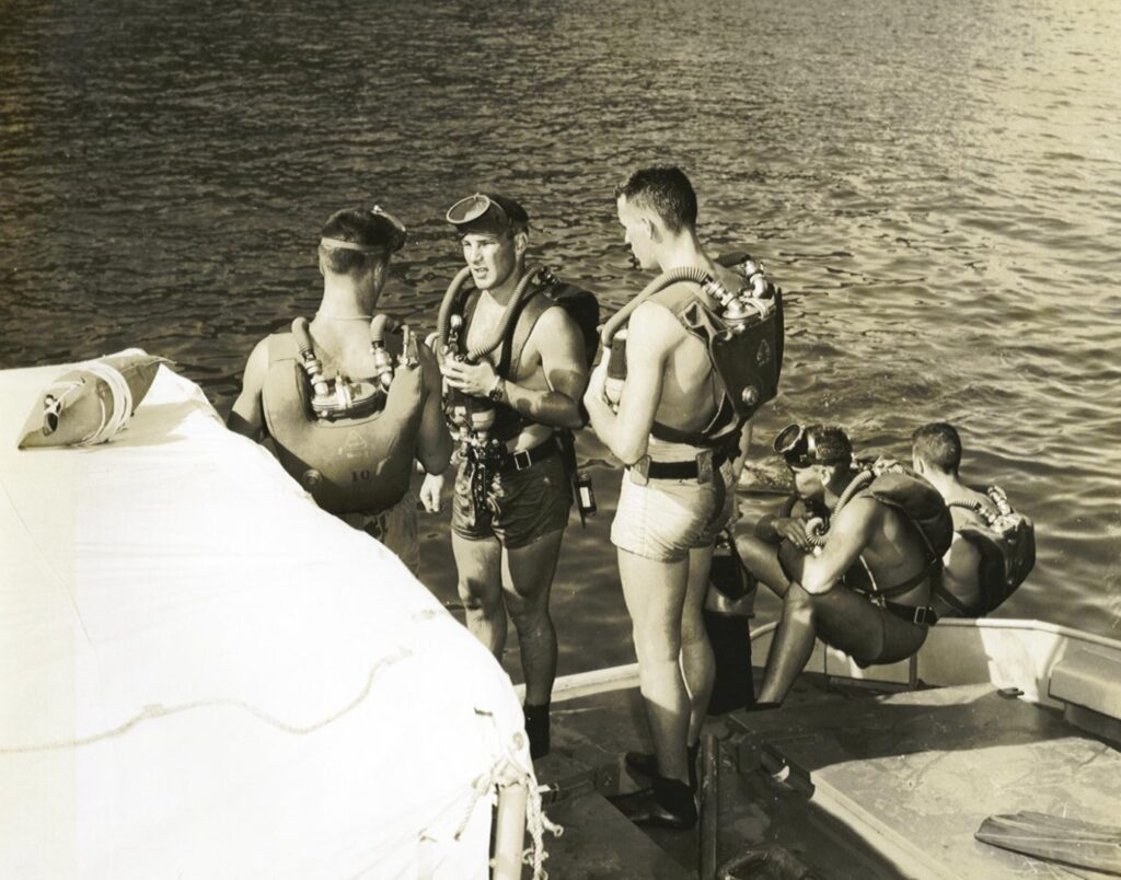
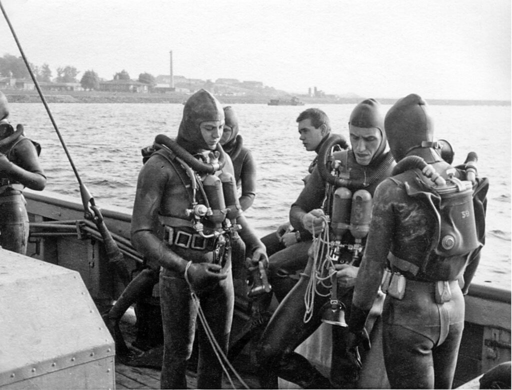
However, early experiences soon showed that the “Dräger 138” was insufficient for this purpose. A manometer was missing.
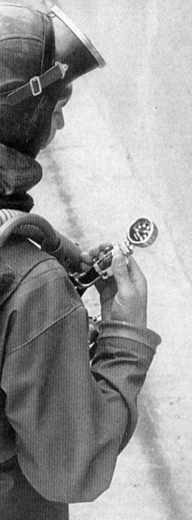
The professional manoeuvrers of the “Froskemenn” students led to significantly higher oxygen consumption than previously experienced in the civilian sector. Continuous monitoring of the remaining oxygen during operations was essential. Thus, the Norwegian frogman school quickly received special versions of the “Dräger 138” with a “foldable” manometer [Image 14][EN10].
This manometer was located at the end of a high-pressure hose, connected to the pressure reducer, in a foldable lockable bracket, which could also be easily read underwater and had luminous figures. The externally guided manometer extension was also used on Dräger compressed air devices at that time. Whether the already delivered “138s” were subsequently retrofitted with manometers or new units with manometers were ordered is not documented.
Endnotes
EN 1 Michael Jung, ” Handbuch zur Tauchgeschichte” Nagelschmid-Verlag, Stuttgart, 1999
EN 2 Michael Seydel, ” Die Entwicklungs- und Nutzungsgeschichte der Tauchretter des Drägerwerkes” 20. 8.2.3: “Strongly influenced by the Italians, the German combat swimmers also used Italian diving equipment. It is unknown why Dräger’s devices were not utilized.”
EN 3 “COMBINED INTELLIGENCE OBJECTIVES SUB-COMMITTEE” G-2 Division, SHAKF (Rear), APO 415
EN 4 Michael Seydel, ” Die Entwicklungs- und Nutzungsgeschichte der Tauchretter des Drägerwerkes ” 2010
EN 5 ” Tauchretter Dräger D2″ a special design for the Danish Navy
EN 6 Paraphrased quote from Lieutenant Commander Herbert Völsch, combat swimmer of WWII and first training director of the Bundesmarine’s combat swimmer company, co-founder of VDST and DUC Krefeld, whom I met at age 17 as a member of DUC Krefeld (member No. 13) in 1963 and who brought me to the Bundesmarine: “Boy, come to the Navy, there you can dive!”
EN 7 Michael Jung ” Das Handbuch zur Tauchgeschichte ” Stephanie Naglschmidt Publishing Stuttgart 1999
EN 8 Archive, National UDT Navy Seal Museum, 3300 N Hwy A1A, Fort Pierce, FL 34949, USA
EN 9 Dräger Document Archive, meeting note from 12.12.1952
EN 10 Dräger Image and Document Archive
Conversations and Correspondence
- Achtert, W., former combat swimmer of the Bundesmarine
- Birkeland, E., former “Sjef for norsk marinens Dykkerog Froskemannskole” Norway
- Haux, G., personal conversations of recent years
- Höner, J., combat swimmer of the German Navy
- Jørgensen, S.-E., Danish Society for Historical Diving, diving historian
- Kahrs, B.W., former instructor at “Comex Diving” and diving historian
- Müller, K., former mine diver of the Bundesmarine
- Phalén, W., former combat swimmer of the Swedish “Kustjägarna”
- Sartor, W., former development engineer at Drägerwerke
- Sassen, U.W., former combat swimmer of the Bundesmarine
Literatur
• Boczek, W., Hilbert, J.: „Tauchen mit Sauerstoff-Kreislaufgeräten“, Delius Klasing, 2008
• Donald, K.: „Oxygen and the Diver“, SPA limited, Britian, 1992
• Ehm, O. F. et al.: „Tauchen noch sicherer“, Müller Rüschlikon, 2003
• Haux, G.: „Typisch Haux“, Haux Publishing, 2002
• Haux, G.: „Tauchtechnik“ Band I + II, Springer-Verlag 1969
• Hesselmann, H.: „Sabotage unter Wasser“, Zeitschrift Delphin, 12/68 – 09/69
• Jørgensen, S.-E.: „Udvikling af iltapparatet (kredsløbsapparatet)“
• Jung, M.: „Handbuch zur Tauchgeschichte“, Naglschmid, Stuttgart, 1999
• Jung, M.: „Sabotage unter Wasser“, Mittler & Sohn, Hamburg, 2004
• Kahrs, B.W.: „NORSK DYKKING“, Kolofon Forlag, 2014
• Krange, E.: „FRA MARINEDYKKINGENS HISTORIE I NORGE“, Erkra Forlag Kristiansand, 1994
• Seydel, M.: „Die Entwicklungs- und Nutzungsgeschichte derTauchretter des Drägerwerkes“, 2010, Müller, M.: „Ägäis 1942“ (1. Kreislaufgerät von HH) TH2 2014 S. 13
• Stelzner, H.: „Gegenlunge und Badetauchretter“, Dräger-Hefte, Nr. 139, Juli 1929
• Stelzner, H.: „Tauchertechnik“, Verlag Charles Coleman Lübeck,1943
• Ulmer W.T.: „Die Lungenfunktion. Methodik und klinische Anwendung“ 2003, Thieme ISBN 313448806X
Notes
- Federal Archives (Military Archive), Freiburg
- Federal Office for Military Technology and Procurement, Koblenz
- Drägerwerk: various user manuals for Dräger oxygen breathing devices, Lübeck
- Drägerwerk: image, document, and device archive, Lübeck
- Combat Swimmer Company, Eckernförde
- Command of the Naval Weapons, Kiel
Page 1 of Part 2 of 4
space 1
space 2
space 3
space 4
PART 2
Dräger Diving Devices for “Combat swimmers”
Chronological development of closed-circuit oxygen scuba diving equipment from the Dräger factory for military use
By Helmut Knüfermann
Part 2 of 4, Devices in “Vest” design type 2
Oxygen Diving Apparatus “Leutnant Lund I” (Dräger-Kleintauchgerät Model 138L)
It was foreseeable that the operations with the initially used “Dräger Small Diving Devices Model 138” could not be satisfactory for military operations in the long run. Therefore, new developments took place. At the end of 1953, Lieutenant Lund, together with chief engineer Hermann Tietze at Drägerwerk in Lübeck, designed an improved oxygen closed-circuit device according to his specifications.
The primary requirement was a longer operational duration. This new oxygen closed-circuit diving device, initially referred to by Drägerwerk as the “Dräger Small Diving Device 138 L” (Lund), eventually received the official designation “Leutnant Lund I”.
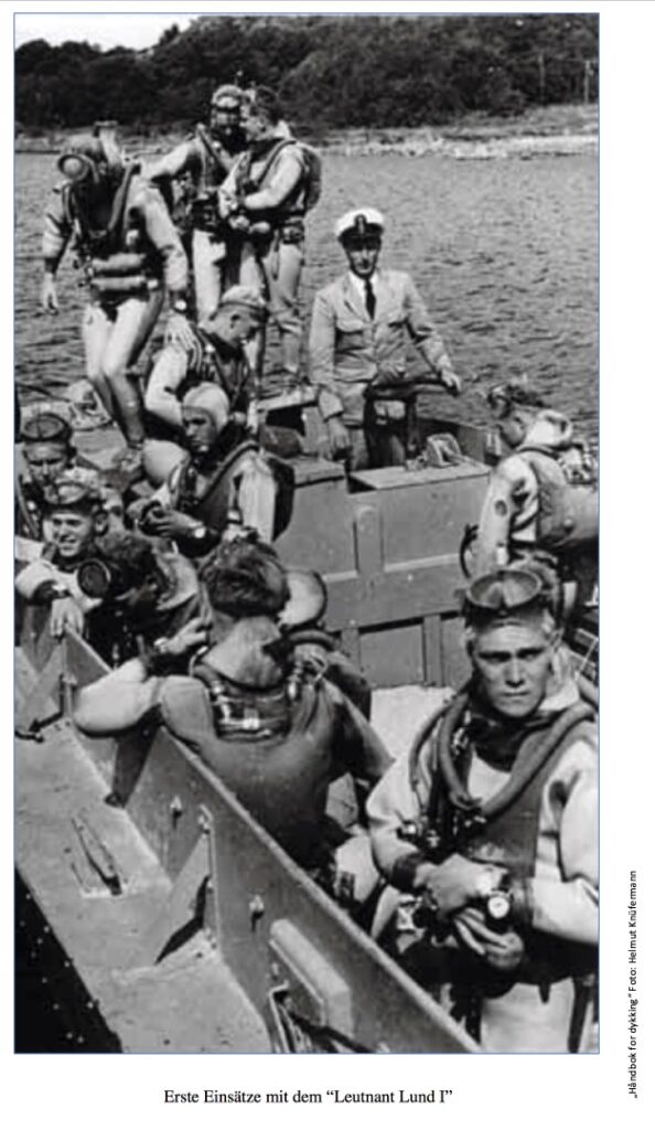
The description below is detailed, as the “Leutnant Lund I” served as the basis for the subsequently described closed-circuit diving devices in “vest” construction. With the “Leutnant Lund I” [Image 15], a device was created in the same construction as the “Dräger Small Diving Device 138,” but with two horizontally arranged oxygen bottles on the chest panel, each containing 0.8 liters, instead of one bottle with 0.6 liters as previously. With an increased filling pressure of 200 bar, the diver now had 320 liters of oxygen available instead of 90 liters.
As the supply of breathing gas is not the only factor limiting the use time of closed-circuit oxygen devices, but also the amount and CO2 absorption capacity of the soda lime, the soda lime container also received a larger filling volume from one to two liters. The maximum dive time was now approximately 90 minutes, with an average oxygen consumption of up to 2 l/min easily covered.
The position of the oval soda lime container in the breathing bag itself had the advantage, as with almost all closed-circuit oxygen devices in “vest” construction, that the soda lime retained good CO2-binding capacity in the ambient warmth of the exhaled air even at low water temperatures.
Picture 15: First missions with the “Leutnant Lund I” in 1953. Source: “Håndbok for Dykking I Navy, KNM Tordenskjold,Dykker- og froskemannsenteret”
In hard-shell devices of later generations, where the soda lime container is installed separately and directly surrounded by ambient water, separate insulation helps prevent cooling, which can reduce the service life of the soda lime by more than half at temperatures around 4 °C and below. As pure oxygen was used as breathing gas, the operating depth—like with all closed-circuit devices—was theoretically limited to about 7 meters due to oxygen toxicity at an O2 partial pressure of 1.6 bar, but practically to 10 meters (due to never having 100% O2 concentration in the breathing bag).
The pressure reducer of the same design as for the “Dräger 138” also had a constant dosing set to 0.9 l/min, which could also be spontaneously increased with a larger oxygen flow through the integrated hand-addition valve. This functionality kept the oxygen amount constant over the entire bottle pressure and diving depth range. This pressure reducer, which Drägerwerk built in the same and slightly modified construction for various breathing devices, is also found in the oxygen closed-circuit diving devices in “vest” construction described in this article. The technical drawing [Image 17] and functional description therefore apply equally to all these mentioned devices.
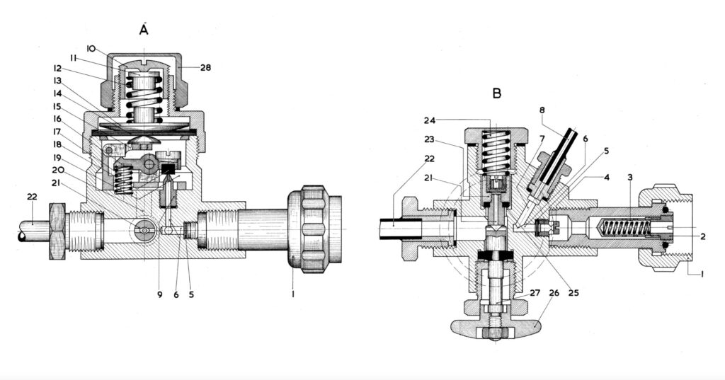
Function of the Pressure Reducer of Dräger Oxygen Closed-Circuit Diving Devices in “Vest” Construction:
The pressure reducer is connected to the oxygen bottle (1) with a G3/4″ union nut. A nozzle (2) holds and centers a very fine rod filter (3). Through this transition to the further nozzle (4), the oxygen passes through a 3-layer membrane (5), which retains the smallest impurities to the channel (6). From here, a branch channel (7) leads to the manometer hose (8). The channel (6) continues in an angled bore (9) to adjust the medium pressure reducing valve.
The medium pressure of the reducing valve can be adjusted by setting the sealed ring-slot screw above (18). From there, the gas reaches the pressure piston (11) with the spring (12), the pressure disc (13), and the membrane (14), which regulates a continuous oxygen supply of 0.9 l/min and can be adjusted through the slot in the union nut (10).
Through the pressure cap (15), the membrane (14) swivels into its resting position. The valve (16) causes the reducing valve (18) to lift and allows the oxygen from the channel (6) to flow into the cavity (19). Once the pressure rises to about 4.5 bar, the oxygen pressure on the membrane (14) increases, overcoming the counterpressure of the spring (12) and the closing spring (17), and can now move the valve (18) to close the oxygen supply.
The oxygen addition is triggered by manually pressing the button (26), which releases the cone valve (21) against the spring (24) for the duration of the press through the pressure piston (27), allowing an oxygen flow from the medium pressure area (19) with a flow rate of about 14 l/min.
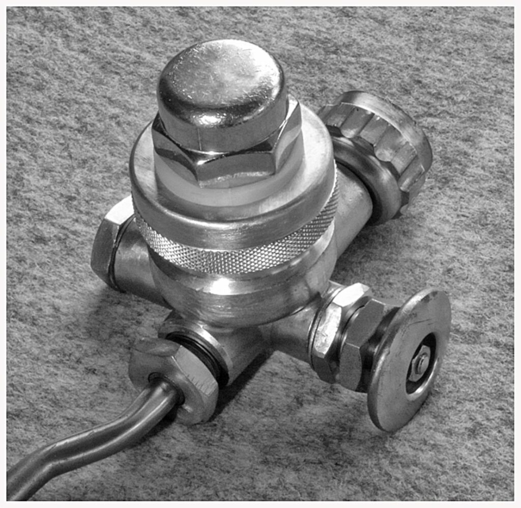
A in [Image 17] shows a vertical section through the pressure reducer and B a horizontal section with a dosing nozzle and the “hand addition valve”. Just like the pressure reducer [Image 18] (here with manometer connection), the mouthpiece with shut-off valve was also adopted from the “Dräger Small Diving Device 138”, as well as the inhalation and exhalation valves, the overpressure valve in the breathing bag, and the foldable manometer for controlling the bottle pressure during diving.
The breathing bag on the back received a new shape compared to the “Dräger 138” with two bulges on the right and left above the soda lime container access [Image 19]. The snug fit on the body and the favourable shape, especially the bulges at the shoulder area, provided excellent breathing resistance in any position and stabilized the swimming position [Image 20].
As a result, the volume of the breathing bag increased slightly from about 7 to 8 liters compared to the “Dräger 138”. The pocket for balancing weights was now placed on the side of the breathing bag facing the diver’s back.
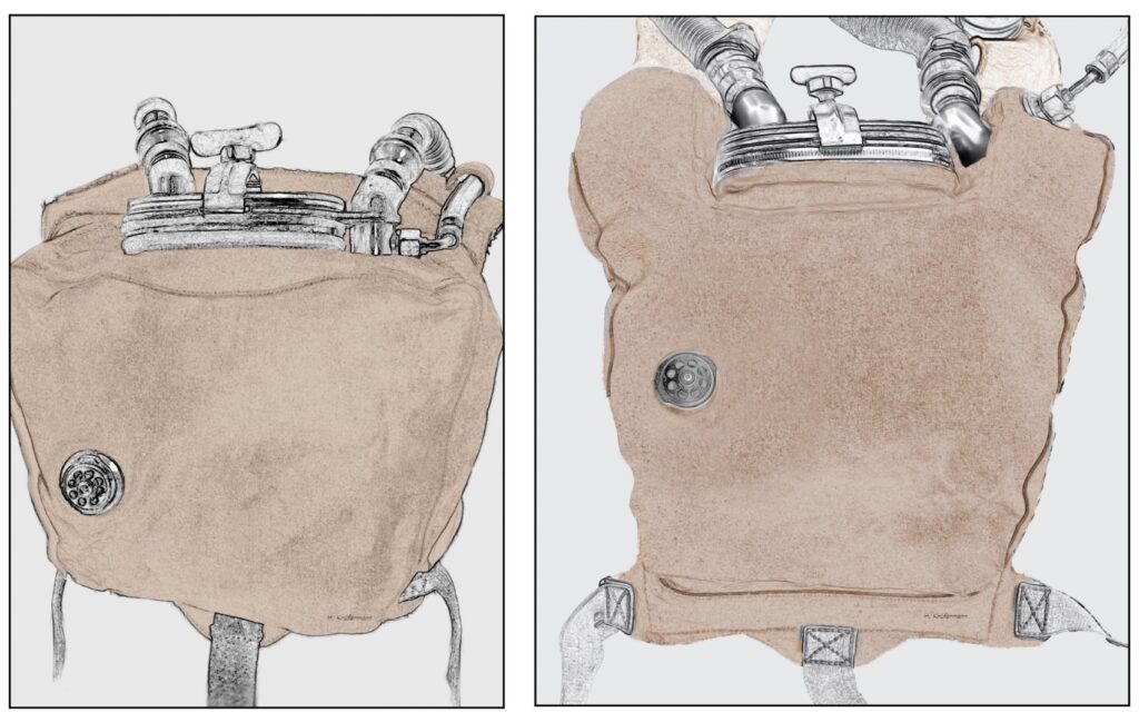
Image 19 Comparison of the breathing bag shapes, left: “Dräger Small Diving Device 138”, right: “Leutnant Lund I + II”. The breathing bags of the closed-circuit devices “Leutnant Lund I and II” received a new shape with two bulges on the left and right above the access to the soda lime container, unlike the “Dräger Small Diving Device 138”. Graphic: H. Knüfermann
The breathing valves of the “Leutnant Lund I” were located in the device-side hose connections [Image 21 left] and contained valve discs made of “mica,” a mineral from the group of “sheet silicates.” Dräger used these in valves for several breathing devices. Mica valve discs were very light, functioned durably with much less wear than the then-common “flap valves” made of rubber, and had high stability. However, the small, lightweight precision pressure spring made of stainless-steel spring wire for pressing the valve discs was the weak point of the construction [Image 22 right]. The high concentration of O2 and CO2 in the breathing air led to a redox reaction even with this treated steel, resulting in frequent replacements.2
The successor to this “Leutnant Lund I,” the Dräger “Leutnant Lund II” (see further description), later received a new lightweight rotary valve mouthpiece made of sea-water-resistant polymer with integrated breathing valves and valve discs with pronounced viscoelastic behaviour. The elastic properties of these new “rubber flap valves,” which are still commonly used in almost all breathing valves today, made a pressure spring unnecessary.
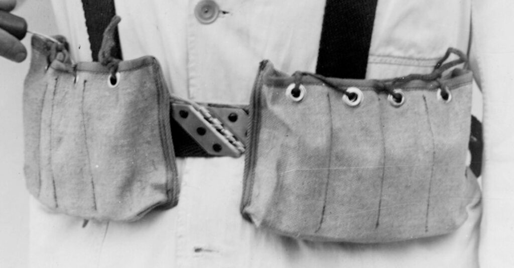
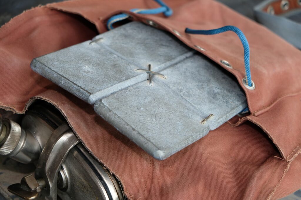
Although pure oxygen closed-circuit devices are generally dived without a buoyancy unit, there must be a balance between buoyancy and weight. To achieve this hydrostatic balance, especially flat lead weights shaped for the rear pocket of the vest were provided for the “Lund I” [Image 23]. At a maximum diving depth of 10 m, the optimal “hovering state” of the device was between 4 and 5 m with a slightly filled breathing bag 3.
Inhalation and exhalation (according to Archimedes’ law), as well as manual addition of oxygen via the hand valve during descent, or release of the excess gas via the nose and mouth nose and mouth during the ascent finely tuned buoyancy control. This of course included the buoyancy of the of the diving suit, which additionally had to be compensated with a weight belt. “Diver safety collars” (not intended for buoyancy adjustment) like those used on later hard-shell combat swimmer devices (LAR) worn on the chest were not common for devices in “vest” construction.
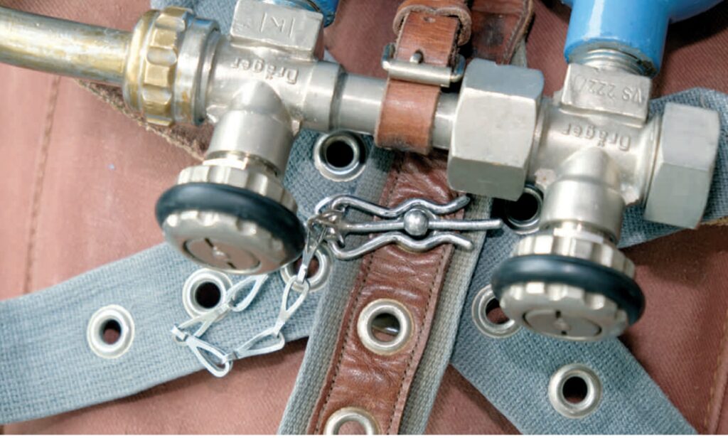
The quick donning and doffing of an oxygen closed-circuit device is essential for military operations. This requires a carrying and fastening system that can be handled blindly even underwater. The vest, consisting of front and back parts, was lifted over the head at the shoulder sections and lowered onto the shoulders through the neck opening; O2 bottles in front, breathing bag in the back. The two parts of the vest “are secured against each other by two side straps and a crotch strap, which are hooked onto the bolts of the quick-release mechanism”…. “First, the crotch strap is hooked onto the bolt, then the side straps are passed through the side loops of the chest part and also secured on the bolt one after the other. A locking pin prevents the straps from slipping off again.”(“werden durch zwei Seitengurte und einen Schrittgurt gegeneinander gesichert, indem sie auf den Bolzen des Schnellöffnungsorgans gehakt werden“…. „Zuerst wird der Schrittgurt auf den Bolzen gehakt, danach werden die Seitengurte durch die seitlichen Ösen des Brustteils geführt und nacheinander ebenfalls auf dem Bolzen festgelegt. Ein Sicherungsstift hindert die Gurte, wieder abzugleiten“4
By today’s standards, this attachment variant may seem somewhat “prehistoric” and hardly allow for quick donning and doffing of the device. However, former combat swimmers of the 1950s and 60s confirm the opposite. Sufficient training led to astonishing records. The central closure [Image 25] could be opened with a single hand movement, allowing the diver to quickly separate from the device.
This new “Leutnant Lund I” understandably brought significant improvements in operational possibilities for more extensive tactical undertakings. It was used not only by the “Froskemenn” of the Norwegian Navy but also found buyers in limited quantities among other Scandinavian naval units [Image 26]. Further delivery to other nations probably hardly took place, as the Drägerwerke already completed the “Leutnant Lund II” a few months later.
2 Analysis Dräger SAFETY, March 2003, on the occasion of the last possible Dräger repair of my own “Leutnant Lund II”
3 Personal experiences from decades of diving with the “Leutnant Lund II”
4 Original text, Dräger user manual “Leutnant Lund II”
The Oxygen Diving Apparatus “Leutnant Lund II” (Dräger Drawing No.: T3600)
For many, the “Leutnant Lund II” diving apparatus is the epitome of a legendary closed-circuit oxygen device. Manufactured by Dräger-Werke from 1954 in collaboration with Lieutenant Lund, the first commander of the “Marinens Froskemannsskolen Horten” in Norway, it was used worldwide by numerous naval units until the mid-1960s. Although designed exclusively for military use, it also found its way to civilian divers here and there. Even today, the “Leutnant Lund II” is highly sought after and has lost none of its mystique.
Even though the “Leutnant Lund II” had considerable renown, it was, with a few changes, an identical copy of the “Leutnant Lund I.” In principle, the “Lund I device,” with which the frogmen of the Norwegian and other Scandinavian navies operated, was largely mature and suitable for military use. However, there was soon a need for technical corrections, which Lund (by then Captain Lieutenant) had implemented according to his specifications and in consultation with chief engineer Hermann Tietze.
The biggest problem was the regularly occurring malfunction of the overpressure valve. The overpressure valve of the “Leutnant Lund I” was taken from the “Dräger Small Diving Device 138,” where it worked reasonably reliably for civilian use for many years. However, the valve on the back of a combat swimmer device experiences greater stress in use and quickly fails. Disassembly and cleaning of the valve were a daily occurrence.
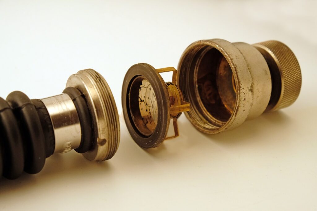
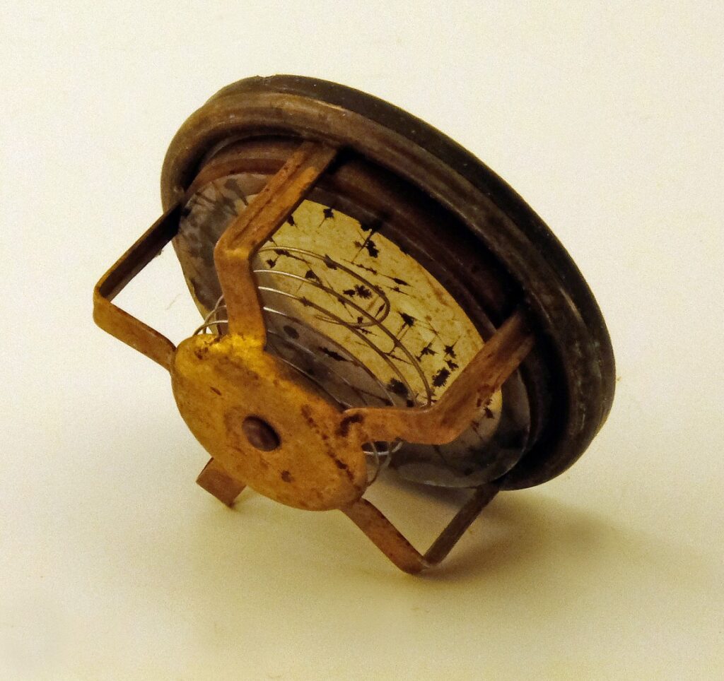
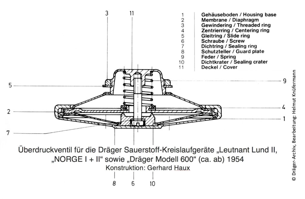
Gerhard Haux, later chief engineer of Dräger-Werke, received the task from his then-boss Hermann Tietze in his younger years to design a new overpressure valve [Image 27] for the “Leutnant Lund device.” Mr. Haux wrote in 2002: “Among the many details that needed improvement at the time, I must particularly highlight an overpressure valve for the breathing bag that caused constant trouble in its original design. Executed as a pure brass construction and equipped with a laboriously fitted spring-loaded sealing cone, this valve became leaky even with the slightest contamination. Not to mention so-called cold welding, which prevented the valve from opening correctly after longer storage. Eventually, I found a solution that solved all problems at once. The new overpressure valve for breathing bags was equipped with a membrane translation. Sealed on a stainless-steel seat with a relatively soft neoprene membrane, reinforced by a precisely balanced spiral spring. The valve opens with the desired setting extraordinarily reliably, precisely, noiselessly, and is immediately ready for use even after months of inactivity. The susceptibility to contamination is minimal because any foreign body on the sealing seat is elastically enclosed by the soft membrane. This development is now over 30 years old but still up to date. What more could a designer want?”
This valve was set to a breathing bag overpressure of 15 cmWS and functioned without problems in the subsequent Dräger oxygen closed-circuit devices in “vest” construction.
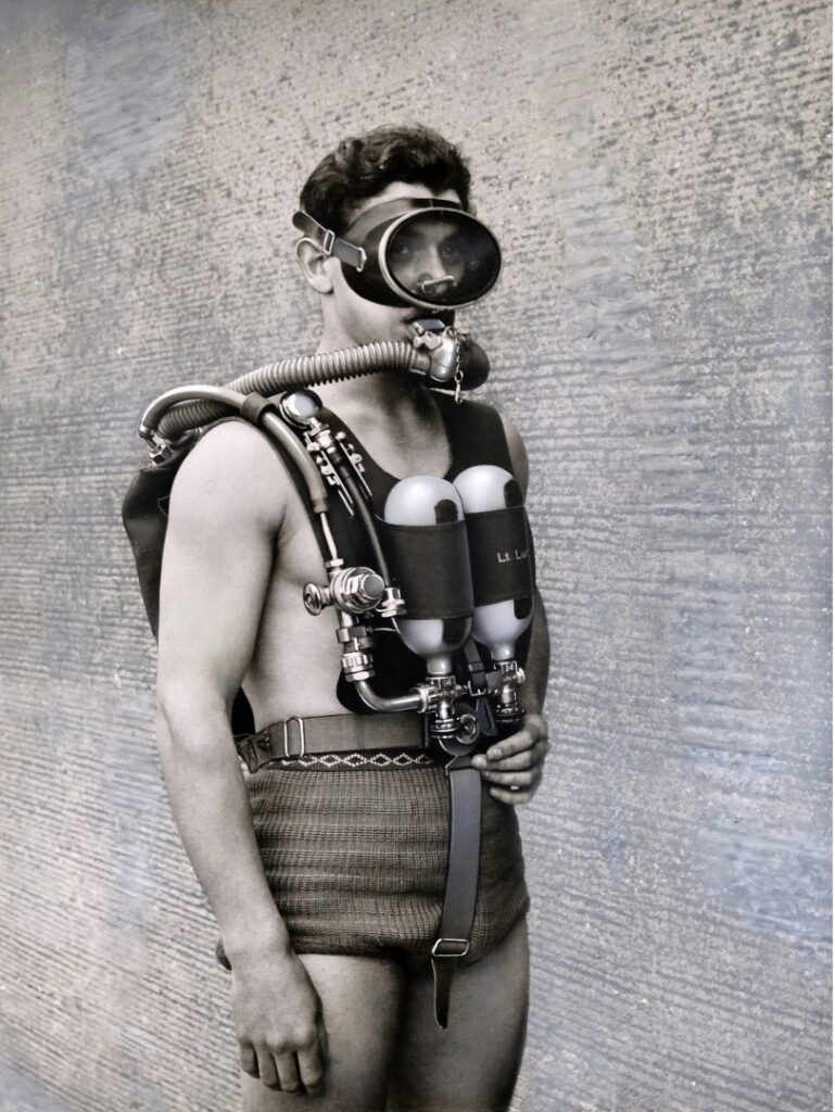
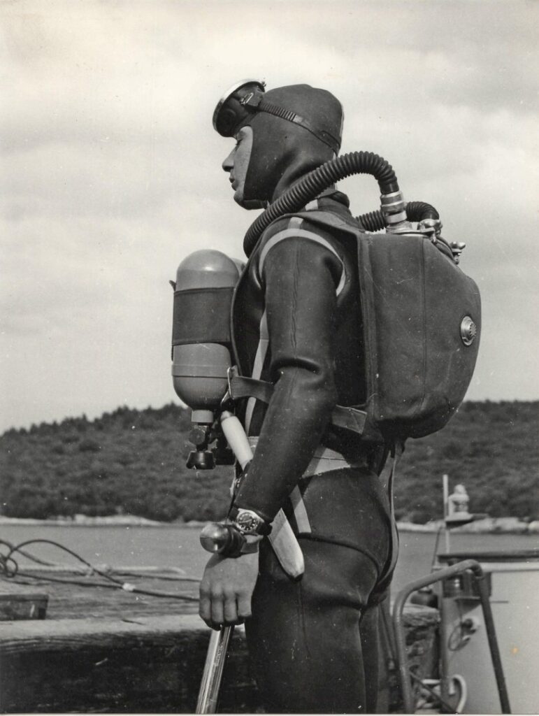
In addition, there was a modification of the oxygen bottle position. The two horizontally arranged oxygen bottles on the chest panel of the “Leutnant Lund I” were “hydrodynamic unfavourable.” They were changed for the “Leutnant Lund II” to a vertical carrying position [Images 28 and 29]. A small but effective correction, which should have a positive impact during longer swimming distances.
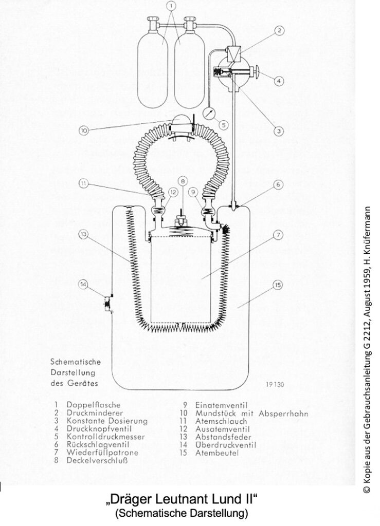
1 Double bottle
2 Pressure reducer
3 Constant dosing
4 Push-button valve
5 Control pressure gauge
6 Non-return valve
7 Refill cartridge
8 Cover cap
9 Inhalation valve
10 Mouthpiece with
stopcock
11 Breathing tube
12 Exhalation valve
13 Spacer spring
14 Pressure relief valve
15 Breathing bag
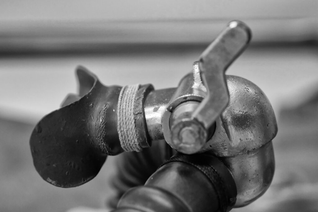
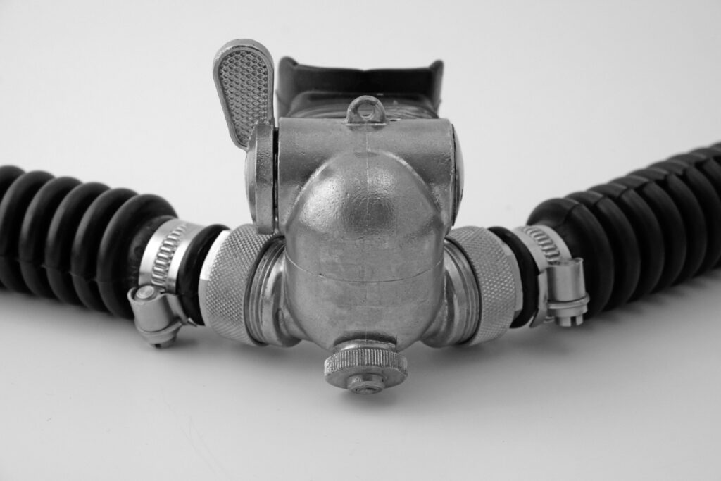
Another change to the “Leutnant Lund I” concerned the mouthpiece.
The inevitable ingress of water into the mouthpiece—especially after resuming use of the previously removed device underwater—and the resulting “gurgling and bubbling” when breathing were not only unpleasant over time but also created noises that, however slight, were transmitted through the water. This did not meet the military requirement for noiselessness.
The only bubble-free solution was to drink or drain the water by turning the body, which could result in wetting the soda lime and reducing its absorption capacity, leading to a dangerous increase in CO2 concentration in the breathing circuit.
Drägerwerke designed a new, also sealable mouthpiece for the “Leutnant Lund II,” but with a hand-operated drainage screw in the extended lower part of the brass housing. Briefly turning this closing screw counterclockwise opened the water-filled area slightly and allowed it to be blown out with a moderate breath while simultaneously pinching the exhalation corrugated hose—a betterment, but not completely bubble-free.
However, the weight of the mouthpiece was so great that a chin support was designed to relieve the jaw muscles [Images 31 and 32]. It was not until the later versions of the “Leutnant Lund II” that a lightweight “rotary valve mouthpiece” made of seawater-resistant polymer was introduced, with built-in control valves that had previously been in the device-side corrugated hose connections, as described.
As with many designs that prompt changes during daily use, details were constantly corrected, which are not further detailed here. “Those who search for mines are closest to God.” This dark humour of the World War II mine seekers remains relevant for the work of mine divers today. The main tasks of minesweepers end where mine clearing devices can no longer operate. These are usually confined spaces, such as harbour basins, canals, or specific points at sea, where mine divers are deployed (today supplemented by underwater drones).
Since sea mines and similar explosive devices register minimal acoustic and magnetic distortions, only special diving devices are suitable for this purpose.
“Leutnant Lund I”.
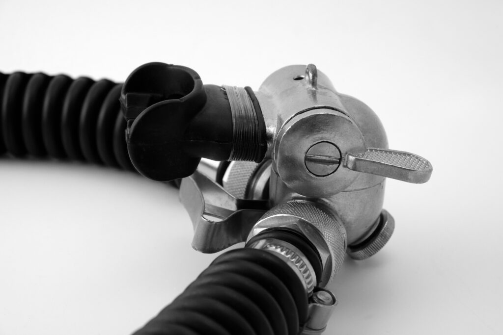
32 right: Mouthpiece of the Dräger rebreather “Leutnant Lund II” with drainage screw and chin rest. Photos: HK
The “Leutnant Lund II” was used for these operations up to a depth of 10 m, but in a “non-magnetic version.” Almost all parts of the device could be manufactured in a non-magnetic version at Drägerwerk. An exception was the oxygen bottles made of a ferromagnetic high-alloy steel.6 “Demagnetization” was required. Dräger arranged the demagnetization (using the alternating field method) for these bottles at the “Magnetic Testing Station Kiel-Friedrichsort” through the “Testing Station 71 for Naval Weapons” in Eckernförde. The demagnetization was carried out from 1956 according to the then-new rules of the NATO Standardization Agreement (STANAG 1131).
Ferromagnetic solids cannot be permanently demagnetized. Magnetic alternating fields in the environment cause the loss of the magnetic signature. Therefore, after measuring the magnetic remanence at intervals, repetitions were necessary.
The question of using non-magnetic lightweight metal pressure bottles made of aluminium would be justified, as the Air Force already used them at that time for fixed installations in jet aircraft. However, the “German Pressure Vessel Regulation” did not yet allow the use of aluminium pressure bottles for “portable breathing devices” at the end of the 1950s.
In addition to the non-magnetic property of military closed-circuit devices, the requirement for noiselessness is an important factor. The acoustic effect of even small bubbles is significant and detectable over greater distances with appropriate underwater sensors due to the underwater sound speed (of 1480 m/s). Passive distance and direction measuring systems filter out the smallest sound sources of different frequency ranges from the consistently present “noise carpet.” The risk of detection when using not completely closed-circuit devices is very high.
The Dräger “Leutnant Lund II,” as well as the other described closed-circuit devices in “vest” construction with constant oxygen dosing and an overpressure valve, did not sufficiently meet this requirement. Occasional unintentional or intentional venting of an excessive gas volume from the breathing bag or through the mouth corners led to bubble formation.
For this reason, the later lung-automatic regeneration devices of the chest-worn “hard-shell” construction (LAR) are much better suited for undetectable operations. They supply oxygen only “on demand,” have no overpressure valve, and possess a hermetically sealed breathing circuit.
However, the lung-automatic functional principle had not yet been developed for Dräger oxygen closed-circuit diving devices at that time. Therefore, the “Dräger-Leutnant Lund II” represented a maximum development stage of military oxygen closed-circuit diving devices for a long time.
Many naval units worldwide adopted the device. It proved itself in countless operations. An overview of the purchasing nations and the quantities produced remains hidden to this day. Nevertheless, this closed-circuit device, alongside English, Italian, French, and American devices, was widely distributed not only in NATO states but also, as mentioned, in eastern states via indirect routes.
Drägerwerke owes the development of the first oxygen closed-circuit swimming diving devices for military use in the early 1950s significantly to the highly dedicated Norwegian naval officer Lieutenant Lund. Therefore, the creation of these devices is also closely linked with the cooperation of the Norwegian Navy and the establishment of the first “Norwegian Frogman School.”7
6 Pressure vessel steel according to DIN 17155
7 “For Drägerwerk, the Norwegian Navy had long been an excellent customer. For example, with the Norwegian Lt. Lund, the famous closed-circuit oxygen devices for combat swimmers were developed, which then carried his name around the world,” wrote Gerhard Haux in 2002 in his book “Typisch Haux.”
Ove Lund, an exceptionally creative and inventive naval officer, not only worked on closed-circuit oxygen devices in collaboration with Hermann Tietze, but also had diving suits manufactured according to his own designs, created decompression tables based on his calculations, developed mixed gas diving devices, as well as compressed air diving devices and pressure chambers, and commissioned further diving technology according to his ideas. He tragically died in the Oslofjord at the age of 32.
In August 1956, he lost his life while attempting to reach a diving depth of 90 meters with his self-designed and Dräger-manufactured (“NITROX”) mixed gas diving device “Leutnant Lund III”. Although the course of the accident is documented, the causes have not been conclusively clarified to this day, more than 60 years later.8
Following the accession of the Federal Republic of Germany to NATO in May 1955, the founding of the Bundeswehr in November 1955, and the reintroduction of military structures in West Germany, the Ministry of Defense set the course for the establishment of new special units. The increasingly tense situation of the “Cold War” further contributed to the prompt establishment of small combat units. Six years after the first deliveries of the “Leutnant Lund I+II” devices by Drägerwerk to various naval units worldwide, the Bundeswehr also equipped the German combat swimmers of the newly established Combat Swimmer Company in 1958 with these devices [Image 38]. By the mid-1960s, the “Leutnant Lund II” in use by the Bundeswehr (and also by other German special units), until it was replaced by the then-new Dräger “LAR II” in hard-shell construction. The tragic accident in which Captain Lieutenant Lund lost his life during a diving attempt off the Norwegian coast did not halt the development of the projects he had initiated together with Drägerwerke. The Royal Norwegian Navy continued the collaboration with Dräger.
The oxygen diving apparatus “NORGE I” (Dräger drawing no.: T10200)9
Combat swimmers are sporadically exposed to particularly high loads. The measured breathing minute volumes 10 of about 30 l/min and an O2 requirement of about 1.2 l/min during moderate fin swimming can increase manifold under high physical demands. Breathing limit values of more than 120 l/min with an oxygen requirement of over 4 l/min are quite possible. The “Leutnant Lund II” reached its limits with this throughput. The cross-sections of the breathing hoses and control valves were too small for these extreme loads, and the breathing resistance increased exponentially. Furthermore, the amount of soda lime in the “Leutnant Lund II” was hardly sufficient to bind the CO2 produced under these loads. Therefore, from 1957 onwards, Dräger, at the request of the Norwegian Navy, produced a modified version of the successful “Leutnant Lund II,” which continued to be produced.
Gerhard Haux, an engineer under the direction of chief engineer Hermann Tietze in Department II of Drägerwerk, developed the oxygen swimming diving device “NORGE.” 11 The “vest” design was similar to that of the “Leutnant Lund”. The oxygen supply remained the same with the pair of 2 x 0.8-liter bottles and a filling pressure of 200 bar, as well as the constant dosing with 0.9 l/min O2 and the possibility of adding O2 through the additional valve. The device also contained the overpressure valve developed by Gerhard Haux in the breathing bag, set with a blow-off pressure of 15-16 cmWS.
The device, however, had the following changes:
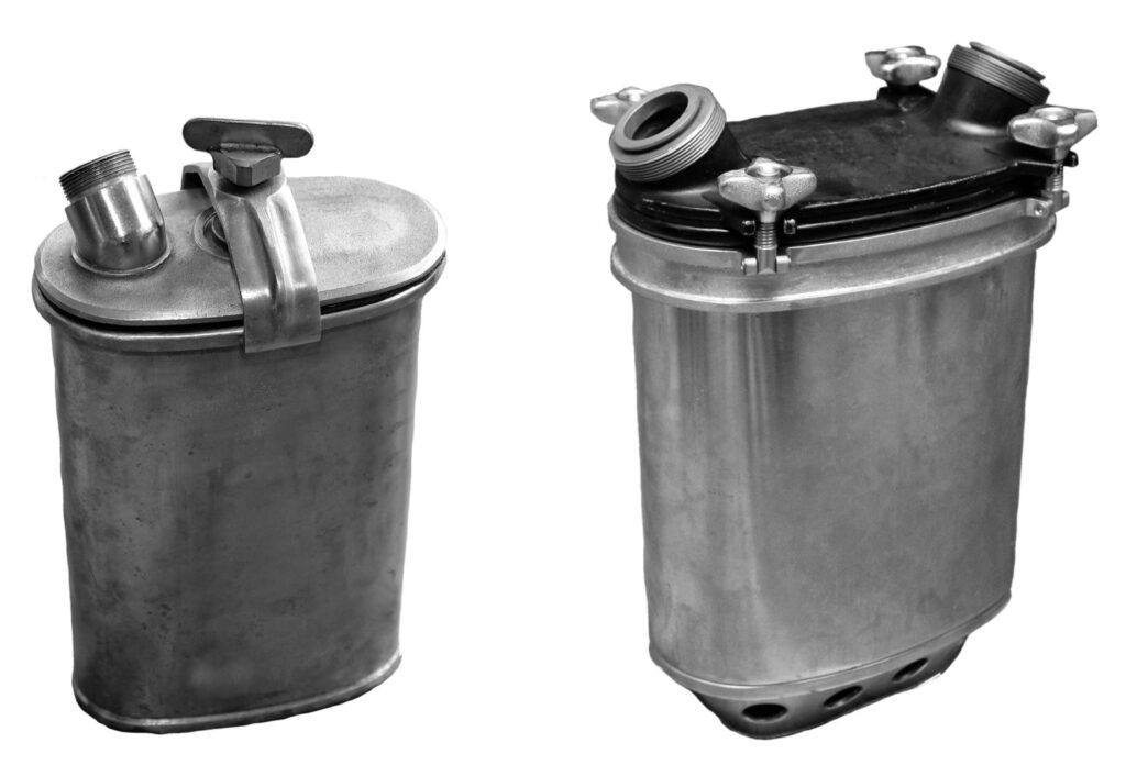
- An enlarged soda lime refill container with a net volume of 3.8 liters (with four closure hand screws for the lid, instead of the previous single closure clamp [Image 39])
- Approximately 60% expanded flow cross-sections of the new breathing hoses
- Correspondingly enlarged flow cross-sections of the control valves in a new rotary valve mouthpiece made of aluminium.
- The pressure gauge directly attached to the pressure reducer block, not foldable.
- A modified, simplified, and slightly enlarged breathing bag shape without bulges at the shoulder area, with a flexible content of 9-10 liters, see comparison [Image 40].
8 Diving History Special, Volume 14/2018, “Leutnant Lund, Biography of a Creative and Inventive Naval Officer”, H. Knüfermann
9 “NORGE I” and “NORGE II”: The “NORGE I” and “NORGE II” devices mentioned in literature and professional articles are referred to in original Dräger documents as “NORGE” and “NORGE I”. This can occasionally lead to confusion. 10 Breathing minute volume: Volume of air inhaled and exhaled per minute 11 Conversations with Gerhard Haux, as well as “Typical Haux”, Haux Publishing 2002
These modifications resulted in a reduction in breathing resistance while simultaneously increasing CO2 absorption efficiency. The reduced flow rate in the large soda lime cartridge led to more effective contact between the breathing gas and the soda lime, ensuring sufficient CO2 absorption even at very high flow rates.
The new design of the “NORGE” soda lime container, in which both the inhalation and exhalation connections, unlike the “Lund II,” led directly into the soda lime container lid, was also associated with a constructive reversal of the breathing gas circuit. Inhalation occurred here from the breathing bag through the soda lime in the container. Exhalation was directed through a closed side path of the soda lime container directly into the breathing bag without renewed contact with the soda lime [Image 41].
The “NORGE II” Sauerstoff-Schwimmtauchgerät (Dräger drawing no.: T5650)
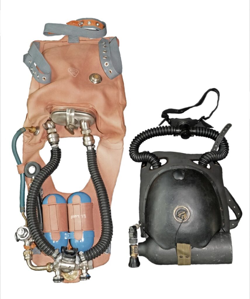
The “NORGE I” and the closed-circuit oxygen devices of the previously described design were made of reddish-brown, partially rubber-coated robust cotton fabric. However, this material became very worn with frequent use and was prone to abrasions. Drying these closed-circuit devices was labour-intensive.
In collaboration with the Norwegian Navy, the decision was made to replace this material with a strong, fabric-reinforced rubber sheet. One of the manufacturers of technical rubber already known at the time, the company “Viking Stavanger A/S” in Norway, supplied in 1959 the black, neoprene-natural rubber coated stretch fabric desired by Dräger on both sides.
The “NORGE II” was created, technically fully identical to the “NORGE I”, but in almost completely black design, including the oxygen bottles [Images 42 and 43]. After making some prototype examples of the vest at “Viking,” further production took place exclusively at the Dräger company, a manufacturing tradition that applied to almost all Dräger products.
©Dräger-Archiv, Foto:HK
This also marked the start of production of the Dräger “NORGE II” in 1960, which replaced the “NORGE I”. The “NORGE II” continued to be manufactured until the early 1970s – albeit in far smaller numbers than the original model of this type of diving apparatus, the “Lieutenant Lund II”. The Norwegian Navy was not the only customer for Dräger NORGE equipment. Both the Swedish and Danish navies used these types of rebreathers in their units12.
12 Kungl: Marinförvaltningen: “OXYGEN APPARATUS FOR ATTACK DIVERS”, Sweden, Type Draeger-Norge I (M 7382-051010) 1964. Jørgensen, S.-E.: “Development of the oxygen apparatus (rebreather) – with a focus on the apparatuses used in Denmark”, 2013. “The first diving apparatus used by the Frømandskorpset was the Lt. Lund II, this was followed by Model Norge I and after this LAR V was adopted”, 02/2018. Krange, E.: “FROM THE HISTORY OF NAVY DIVING IN NORWAY”, Erkra Forlag Kristiansand 1994.
Photo: HK
The “Model 600” Sauerstoff-Schwimmtauchgerät (Dräger drawing no.: T5421) [Fig. 44]
The “net times” of underwater stays for combat swimmers are shorter compared to those of mine or ship divers. A combat swimmer is an “all-rounder” who must also be able to fulfil their mission safely over a wide range of operations above water. Experience shows that a closed-circuit device with an appropriate oxygen supply, such as the “Leutnant Lund” or the “NORGE,” with a usage duration of about 90 minutes, is sufficient for this purpose.
However, in remote and unpredictable amphibious operations with extended timeframes, situations may arise that require even longer usage durations for multiple dives during a mission. Thus, exceptional missions demand corresponding equipment designs.
In April 1965, the engineering department II of Drägerwerk designed the “Model 600” according to the specifications of military clients [Images 45 and 46]. It is likely that the Norwegian Navy was once again the source of ideas for this model, a modified version of the Dräger “NORGE I” with 2 O2 bottles, each with a capacity of 1.5 liters and a filling pressure of 200 bar, corresponding to a 600-liter oxygen supply as breathing gas. According to the user manual, this allowed a usage duration or dive time of 180 minutes, which could be further extended by economical oxygen consumption under light underwater loads.
The large soda lime refill container and the large breathing hose diameters with the correspondingly dimensioned flow cross-sections of the control valves of the “NORGE I” were retained. All other components also matched those of the “NORGE I.” Only the foldable pressure gauge for checking the bottle filling pressure was taken over from the “Leutnant Lund II,” unlike the “NORGE I.”
Despite the lighter oxygen bottles made of aluminium used for this type of device for the first time, the “Model 600” weighed just under 20 kg, certainly less significant underwater. Compared to the weight of the “Leutnant Lund” at about 13 kg and the approximately 15 kg “NORGE,” this was a “sporting challenge” for combat swimmers who also had to carry weight belts and other tactical equipment above water.
From continuous flow to automatic lung control
As effective and successful as all previously described Dräger closed-circuit oxygen diving devices were, they still had a weakness for use in military operations. The constant oxygen flow of 0.9 l/min required regular refilling of the breathing bag using the auxiliary valve by hand in case of higher consumption. If the bottle valve was not closed, a very low oxygen consumption could cause the breathing bag to slowly fill, the excess breathing gas to vent through the overpressure valve, or to be released through the corners of the mouth, sending telltale bubbles to the water surface. Strictly speaking, these were therefore “semi-closed systems,” although described as “closed-circuit oxygen diving devices.”
Meanwhile, closed-circuit oxygen diving devices from foreign manufacturers were known to have their breathing gas supply refilled by an integrated lung demand valve only as much oxygen as the diver consumed, and thus did not require an overpressure valve, essentially fully closed systems. For the Dräger engineers, as well as for the responsible parties of the Federal Navy, this was a consideration to rethink the designs of combat swimmer diving devices.
Gerhard Haux commented on this:13
“In this happy small-scale development time (1960), a French development group with the G.E.R.S. device burst out of the blue. It was a sealed, extremely compact closed-circuit oxygen device for combat swimmers, worn exclusively on the chest, a substantial advance over the Lt. Lund II and the NORGE devices, objectively speaking.”
Thus, in early 1961, also at the urging of the Federal Navy, the first prototypes of a “lung automatic regeneration device” “LAR” in the chest-worn “hard-shell” design began to be developed in Drägerwerk’s Department II, which in the following years replaced the legendary “Leutnant Lund II,” the “NORGE I” and “II,” as well as the “Model 600.” A series of test devices with new insights and modifications in the following years led to the successful “LAR” diving equipment series for combat swimmers, which are still manufactured today in technologically highly developed versions.
Part 3 of this article (in the next issue of Diving History) describes the development of these first Dräger LAR closed-circuit devices in “hard-shell” design.
————————————————————————-
Presentation of the diving devices used by the “SJØFORSVARETS DYKKER- OG FROSKEMANNSSKOLEN” in Norway since its founding until 1997, large-format photos, and a training video at weblink t1p.de/os7a
Many thanks to all those who knowingly or unknowingly contributed to this article. Special thanks to Gerhard Haux and Bjørn W. Kahrs, who provided me with a lot of information that probably no longer exists as written documents, and especially to Thomas Peyn, head of the Dräger equipment and document archive, who gave me access to the historical equipment archive as well as the document archive of Drägerwerke.
Sources see part 1 of the article in Diving History 09 2018/06
13 Conversations with Gerhard Haux, as well as “Typisch Haux,” Haux Publishing 2002 14 “Oxygers 57,” a French closed-circuit diving device, developed by G.E.R.S. (“Le Groupe de Recherches Sous-Marines”, the underwater research group of the French Navy), manufacture and distribution: Fenzy/La Spirotechnique
s1
s2
s3
s4
PART 3
Dräger diving equipment for”Combat Swimmers”
Chronological development of closed oxygen rebreathers from Drägerwerke for the military use under water
Devices in “hard-shell” design
The closed-circuit oxygen diving devices in “vest” design manufactured by Drägerwerke were part of the reliable operational equipment of many combat swimmer units worldwide in the 1950s and 60s. In the course of contemporary development, comparisons were soon made with diving equipment designs from other nations.
Gerhard Haux, then chief engineer at Drägerwerke, described this in his book “Typisch Haux”1 with the following words:
“Into this happy little development time then burst, like a burst out from the blue, a French development group with the G.E.R.S.2 device (Oxygers 57). It was an encapsulated, extremely compact closed-circuit oxygen device for combat swimmers, worn exclusively on the chest, a significant advance over the ‘Lt. Lund II’ and the ‘NORGE devices’, objectively speaking.”
Thus, in Drägerwerk’s Department II and also at the instigation of Wolfgang Brinckmann, Corvette Captain and Commander of the KdoMWa3 of the Federal Navy, the first prototype models of a “lung automatic regeneration device” (LAR) in chest-worn “hard-shell” design began to be developed, which would replace the Dräger closed-circuit oxygen devices in “vest” design in the following years.
With previously manufactured closed-circuit devices in “vest” design with constant oxygen supply, overdosing with low O2 consumption could not be avoided. The result was that excessive gas volume in the breathing bag, vented through the overpressure valve or at the corners of the mouth, caused telltale bubble formation, as well as unused oxygen overconsumption. Conversely, under heavy loads on the combat swimmer and high O2 consumption, refilling the circuit by repeatedly operating the auxiliary valve (often called the bypass valve today) was required. This additional handling, which can be very cumbersome, is avoidable if only as much oxygen is supplied to the circuit as the diver consumes. Therefore, it is a comparatively better solution if the oxygen supply is regulated automatically by a lung demand valve. A lung demand valve in the breathing bag responds to an adjustable negative pressure and ensures the timely refilling of the device’s circuit. The mentioned French G.E.R.S “Oxygers 57” operated on this principle.
1 “TYPISCH HAUX,” Gerhard Haux, HAUX PUBLISHING 2002
2 G.E.R.S “Le Groupe de Recherches Sous-Marines,” the underwater research group of the French Navy (co-founders: Cousteau and Dumas). Manufacture and distribution of the “Oxygers 57”: Fenzy/La Spirotechnique.
3 The “KdoMWa, Command of Naval Weapons in Kiel,” a specialized command of the Federal Navy responsible for all matters of armament. It oversaw schools and testing facilities for naval weapons.
The combat swimmers of the Federal Navy in Germany, equipped with the “Leutnant Lund II” from Dräger, already completed courses at the diving school of the French combat swimmers in St. Mandrier, a school of the “Commando Action Sous-Marine” or “Commando Hubert,” in 1959, half a year after the establishment of the Combat Swimmer Company.
The training there was conducted with the “Oxygers 57.” Compared to the previous Dräger closed-circuit devices in “vest design,” this French device was not only significantly smaller and lighter but also considerably more user-friendly for the same usage duration [Image 01]. The chest-worn design kept the back free for tactical additional equipment and allowed for very quick donning and doffing during operations. It was largely non-magnetic with an aluminium oxygen bottle, had a completely closed breathing circuit without an overpressure valve, and featured a lung demand valve instead of an O2 auxiliary valve (bypass), whose response pressure could be adjusted during the dive.
The experiences made by the German combat swimmers with this closed-circuit device were so convincing that the “Federal Office for Military Technology and Procurement” approved a request from KKpt Brinckmann in July 1960 to purchase 10 “Oxygers 57” diving devices for testing and as an impetus for an initial Dräger-LAR construction. The order was placed with the manufacturer Fenzy and delivered to the Federal Navy through the then importer Jack W. Lavanchy4 at a price of DM 1,390 per unit.
These 10 units were to be initially tested by mine divers in the swimming pool of the Navy Supply School in List on Sylt, according to the instructions of the Federal Office for Military Technology and Procurement from July 1960, and later by combat swimmers in open water.
The obvious idea of designing the first LAR device based on the “Oxygers” model was not put into practice.
realised. The manufacturing company Fenzy made the contractually the condition to be contractually signed,
“…that the German Armed Forces would neither make a replica nor be organised”. However, the Dräger engineers had their own ideas anyway, especially as Bernhard Dräger had already developed an oxygen lung power-operated oxygen dosing >>depression automaton<< 5 and in the course of the following decades
this “LAR” control system in mining equipment with closed-circuit breathing with circulatory breathing.
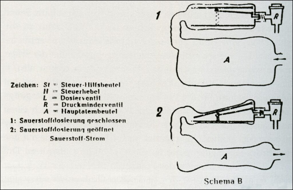
Drawing 03: Lung regulator >>Depression regulator<<5, scheme B – with main and auxiliary and auxiliary breathing bag, and control lever, schematic drawing 1919 by Bernhard Dräger. Source: Manuscript by J.W. Haase-Lampe, © Lisa Dräger Lübeck, 2007
Furthermore, based on Dräger’s extensive experience with respiratory and closed-circuit devices for mining, diving operations, and rescue, the initial basic ideas could soon be put into practice.
Primary requirements according to the specifications for the first Dräger-LAR design were:
- Lung-automatic oxygen supply, no constant breathing gas flow
- Completely closed circulation system
- No overpressure valve
- Separate inhalation and exhalation hoses
- Housing made of fiberglass-reinforced polyester resin
- Worn entirely on the chest
- A single oxygen bottle lying horizontally below the housing
- Lung demand valve, breathing bag, and soda lime container integrated into the protective housing.
Today, Dräger implements complex planning and design tasks from idea to production without significant time losses, in coordination with project and product management, and with the help of specialized software.
4 Jack W. Lavanchy, 1929-2016, diving pioneer, Switzerland, took over the exclusive distribution for La Spirotechnique in Switzerland from May 1965 and in 1968 also for Germany.
5 based on an original idea by the Frenchman Rouquayrol from 1872 (high-pressure fresh air apparatus).
In the 1960s, however, various engineers worked in parallel with “analog” methods and their own ideas for the same project, from which a final approved version was eventually chosen.
Among other things, there was a design labelled “R181,” which Gerhard Haux personally tested in Dräger’s own swimming pool [Image 04]. The impressive small design of the “Oxyger 57” likely led to the construction of this design in the fall of 1960. Data or descriptions could no longer be determined.
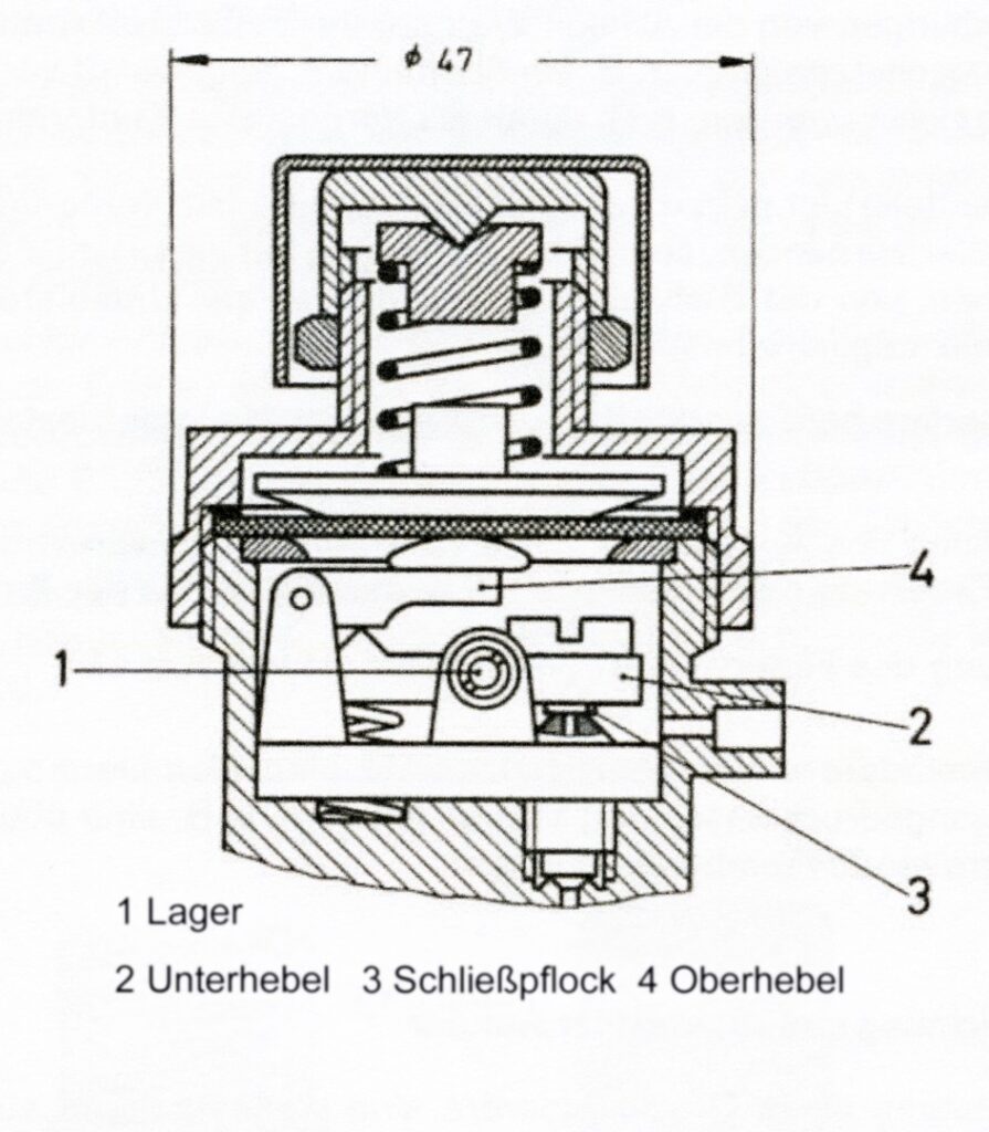
After some experimental setups at the beginning of 1961, a first LAR prototype was able to “make the leap from the drawing board to the swimming pool” [Image 05]. Most of the components came from the serial production of existing respiratory protection devices. When selecting a pressure reducer, which reduced the oxygen requirement from a 1.5-liter (steel) bottle with 200 bar high pressure to a low pressure of 3 to 5 bar, they chose an already tested version. A model with very good control accuracy and a double lever mechanism (“Dräger-Z-Werk”) that closed against the supply pressure at low gas flows was used, which was already working perfectly in existing oxygen gas protection devices.
The second stage was embodied by a slightly modified single-stage lung regulator of the “PL 67 model” compressed air hose device with a rocker valve, which was centrally integrated into the breathing bag [Image 07]. The inhalation chamber of this regulator was connected to the pressure conditions prevailing in the breathing bag of the device [Image 08].
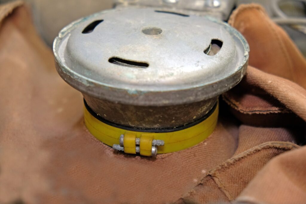
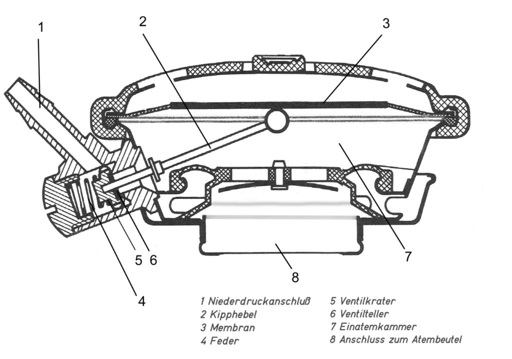
Depending on the filling level of the breathing bag, inhalation created a negative pressure that opened the rocker valve via the membrane, ensuring a supply of oxygen.
The permanently installed lime container made of metal had a capacity of about 1.8 liters and could be refilled through a laterally attached lid opening. The breathing bag, made of fabric rubberized on one side, provided a flexible volume of about 8 liters. The inhalation and exhalation valves were located in the lockable slide mouthpiece made of PC (polycarbonate). The basic functions of this “rough version” were acceptable for the time being. They immediately led to the construction of the “LAR I.”
The LAR 1
The beginning of a successful Dräger diving equipment series (Order number T5370).
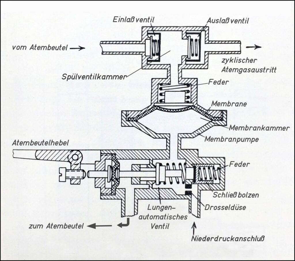
The experimental model “LAR 0” [Image 10] was the basis for the “LAR I”. It was equipped with a – at the time considered necessary – respiratory physiologically suitable component, a “flushing pump”.
In contrast to the purity of today’s oxygen in compressed gas cylinders used for breathing, with 99.999% purity, the O2 content at that time was only about 98%. One of the lightweight Dräger respiratory protection devices with a closed oxygen circuit from the 1950s, the “Dräger Mining Device BG 170/400,” was already equipped with this flushing pump. Its task was to remove the remaining 2% of “unbreathable gases” – mainly nitrogen – from the breathing circuit.
Additional factors were not decisive for the support by a flushing pump but should also not be disregarded. On one hand, the residual nitrogen from the lime container and the residual volume of the lungs increases the inert gas content. On the other hand, the nitrogen bound and released from the body tissue must also be taken into account.
The inspiratory N2 inert gas absorption does not increase with pure O2 breathing (including hyperbaric). There is no saturation of nitrogen, as it is absent in the breathing circuit. However, under the conditions of pure oxygen breathing, an (exponentially progressing) N2 desaturation occurs, depending on various solubility coefficients in body tissue groups. This is also noticeable, albeit to a small extent. The volume, depending on body weight, amounts to about 1.0 to 1.3 liters in total.
Test series with combat swimmers showed that even with longer dives and prescribed flushing processes, on average, only 76% oxygen was present in the breathing circuit.6
The flushing pump provided significant safety under these aspects. The “Dräger Mining Device BG 170/400” could be used in rescue operations without time-consuming and repeated pre-flushing of the breathing bag with oxygen.
Therefore, this flushing device was also considered appropriate in a military circuit device and the pump was built into the “LAR I” [Image 11], technically modified for use under water. 7
It was started with each response cycle of the lung regulator. The pump simultaneously drew breathing gas from the breathing circuit through a valve with each recurring opening of the lung regulator and, after exceeding a membrane chamber limit value, pushed this air through the outlet valve of the flushing valve chamber into the open water at regular intervals (the flushing quantity amounted to about 8% of the respective supplied breathing gas). This ensured that no disproportionately high inert gas content could accumulate in the breathing bag.
6 W. Boczek, J. Hilbert “Diving with Oxygen Rebreathers” Verlag Delius Klasing, ISBN 978-3-7688-2422-4
7 Experienced combat swimmers flush today when they spontaneous dive underwater.
As early as the early summer of 1961, the construction and practical tests at Dräger were completed. In July 1961, Dräger was able to offer “10 units of the lung-automatic diving device model LAR I” at a price of DM 1,479 each to the Federal Ministry of Defense. Just 14 days later, the Federal Office of Defense Technology and Procurement received an order to purchase not 10, but 20 units of the “LAR I”.
The devices were to be delivered, half to MVS8 List / Sylt and half to KdoAS9 in Wilhelmshaven, for testing by the respective combat swimmer units in troop trials. Drägerwerke confirmed the order with a delivery time of 8 months. In the spring of 1962, the Bundesmarine combat swimmers could begin testing the first specimens of the “LAR I”. However, over the following months, it became clear that this first LAR design needed to be reconsidered. The conclusion of the test report, which was officially documented only at the end of 1963, was:
“The troop trials conducted with the ‘LAR I’ diving device did not yield satisfactory results. The breathing flushing pump required significant space. The utility of the flushing pump did not meet the expectations placed upon it. The efficiency was too low, the oxygen supply was sluggish and could not adequately meet the oxygen demand—especially during rapid diving. Contrary to previous notions, a bypass valve for the lung-automatic principle of the respiratory system was necessary… The devices are not fit for troop use.” Furthermore, the device did not operate without bubbles due to the gas discharge from the flushing pump. This was the “END” for the “LAR I.”
Whether these converted “LAR I” devices were subsequently used in hall training is not recorded. Notably, in recent years, two of these devices reappeared. They were externally recognizable by a remaining round opening on the left side of the housing, which previously contained a screen to protect the exiting flushing pump air line [Image 13]. These two specimens were (probably later) equipped with 1.5-liter aluminium alloy cylinders each. One of these devices was reviewed in 2017, made dive-ready, and functioned flawlessly during a short open water dive [Image 14].
The LAR II
Construction series with great success (order code T6030)
The agreed delivery dates with the Federal Office of Defense Technology and Procurement (BWB11) made the rapid production of a successor model urgently necessary. “Corvette Captain Brinckmann, Bundesmarine (affectionately also called ‘Kleinkampfbrinckmann’12, put the pressure on us…” as Gerhard Haux wrote in his book “Typisch Haux.” Due to the unsatisfactory test results with the “LAR I,” Dräger immediately developed a new LAR model in 1963 on their own initiative, with a smaller hard-shell case made of fiberglass-reinforced plastic [Image 15] and numerous changes – under the model designation “LAR II.”
A newly designed small lung regulator with a bypass function, which could be operated from the front of the device, the no longer present flushing pump, and the…
8 Marine Supply School, List / Sylt
9 Command of Amphibious Forces, Wilhelmshaven
10 Marine Underwater Weapons School, Eckernförde
11 “BWB” Federal Office of Defense Technology and Procurement
12 Corvette Captain Brinckmann was an active officer of the Kleinkampfverband of the Kriegsmarine
relocating the pressure reducer to the outside of the housing saved space and allowed for a smaller design. Eventually, this resulted in a closed-circuit diving apparatus with the following technical data:
- Moving the pressure reducer to the outside of the housing saved space and thus made a smaller design possible. The result was a rebreather with the following technical features data:
- A new (bolt) pressure reducer with 3.5 bar “back pressure” and overpressure valve
- A new small lung regulator with a bypass button on the front of the device. Trigger pressure individually adjustable using an Allen screw
- A removable round lime container made of lightweight metal, with a capacity of 2.0 liters, and an opening spanning the entire container cross-section for filling
- Removable seawater-resistant fabric breathing bag with an internal natural rubber coating and a volume of approximately 5.5 liters
- Lockable slide mouthpiece made of PE with natural rubber breathing valve discs
- Shorter and more flexible breathing hoses compared to the “LAR I”
- Newly designed harness with quick-release elements
- A manometer to read the bottle pressure from the outside on the right side of the housing
- Oxygen bottle made of steel (later of lightweight metal) with a capacity of 1.5 liters and 200 bar filling pressure
- Largely non-magnetic
- Almost noiseless
- Approximately 3 hours diving time
- Weight approximately 11.5 kg
In O2 rebreathers, the pressure reducer is subjected to only minimal stress. It must simply replace the consumed oxygen (depending on physical exertion, up to over 4 liters/min) in the breathing bag. In contrast, open systems require up to 70 liters/min for respiration (at the surface). Unlike the previous “Z-Werk” version from gas protection devices, the “LAR II” received a new single-stage bolt pressure reducer with an adequate oxygen delivery rate and a constant “back pressure”13 of 3.5 bar required for the lung regulator (Order number T11791).
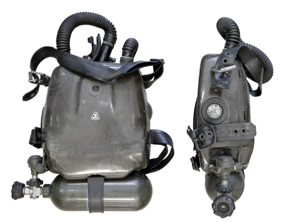
Image 15: The first specimen of the “Dräger-LAR II,” front and right side. A semi-circular cover on the left front side (from the wearer’s perspective) conceals the opening for the installation of the manometer, which was moved from the left to the right side before mass production. © Dräger-Archiv, Photo: HK
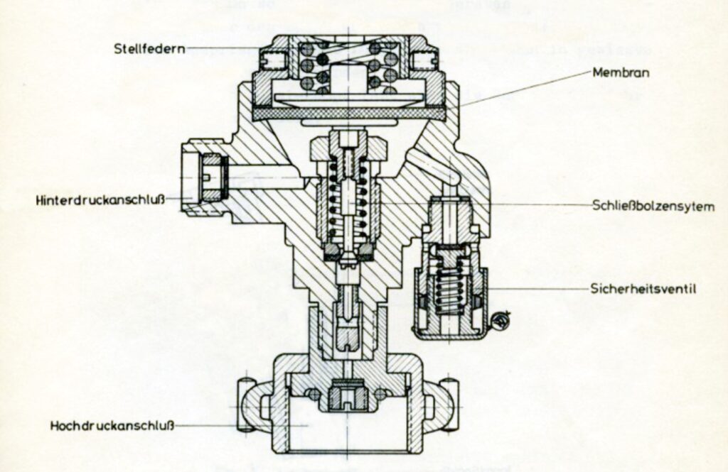
For the design of the new pressure reducer, its suitability for cold water was also was also important. A pressure relief valve prevented the supply gas from flowing of the supply gas into the breathing bag in the event of icing in cold water applications. This This type of pressure reducer can still be found in a modified version in current
LAR models.
13 “Back pressure” = Dräger term, now referred to as medium pressure (MP).
The new lung regulator was specifically adapted to the requirements of an oxygen rebreather. The air delivery rate of the “Dräger-PL 67” initially installed in the “LAR 0” and “LAR I” and designed for compressed air diving was too high and not suitable for the cyclic lung-automatic filling of the breathing bag in a rebreather. All factors—the membrane size, the length of the lever, the diameter of the valve bore, the pressure of the lever spring, and the technical transmission of the “bypass” auxiliary valve—resulted in a small and exemplary design that is still used in today’s LAR [Images 17 and 18] (Order number T12940). The trigger pressure of the lung regulator could be adjusted within certain limits (outside of the water) using an adjustment screw (Allen key SW 3).
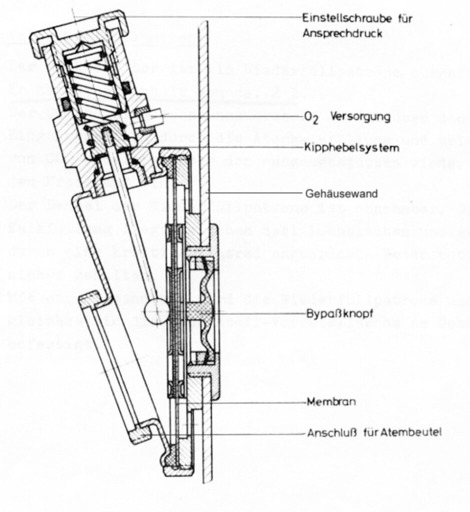
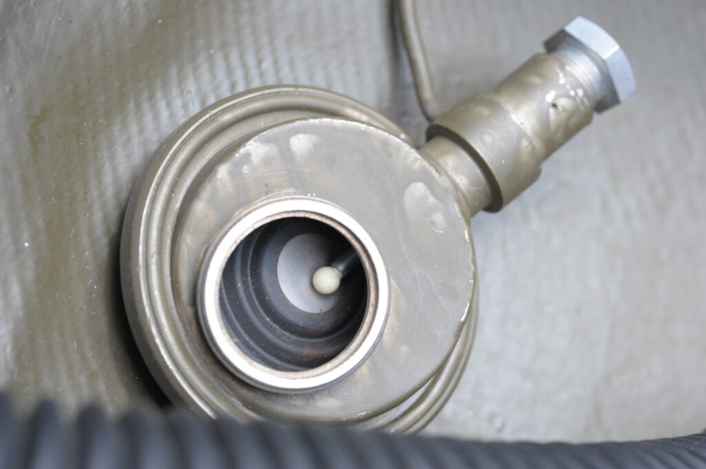
The new non-magnetic lime container with a round cross-section made of a seawater-resistant aluminium alloy (AlMgSi) was removable for refilling and had a capacity of 2 liters. The removable lid on one side of the container allowed the entire cross-section to be open for filling. The lime filling was located between two perforated plates and was securely held in place by a strong, centrally arranged spring [Images 19 and 20]. Depending on CO2 production, ambient temperature, humidity, and (fresh) lime, a usage duration of up to 3 hours could be guaranteed with a single filling.
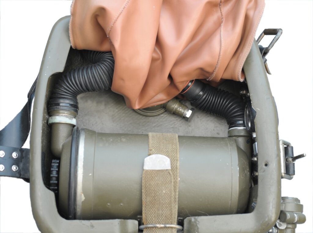
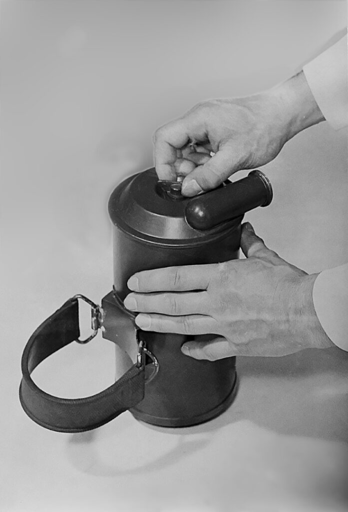
The model “LAR II” thus created was initially tested in January 1964, both technically and physiologically, in the indoor pool of MVS List using an old PL67 lung regulator without a bypass and later with a newly designed bypass lung regulator. The test was repeated two months later by engineer Gerhard Haux from Drägerwerke and Corvette Captain Brinckmann from KdoMWa, both at the Dräger plant and in the swimming pool of MVS List, supported by two divers from MUWS.
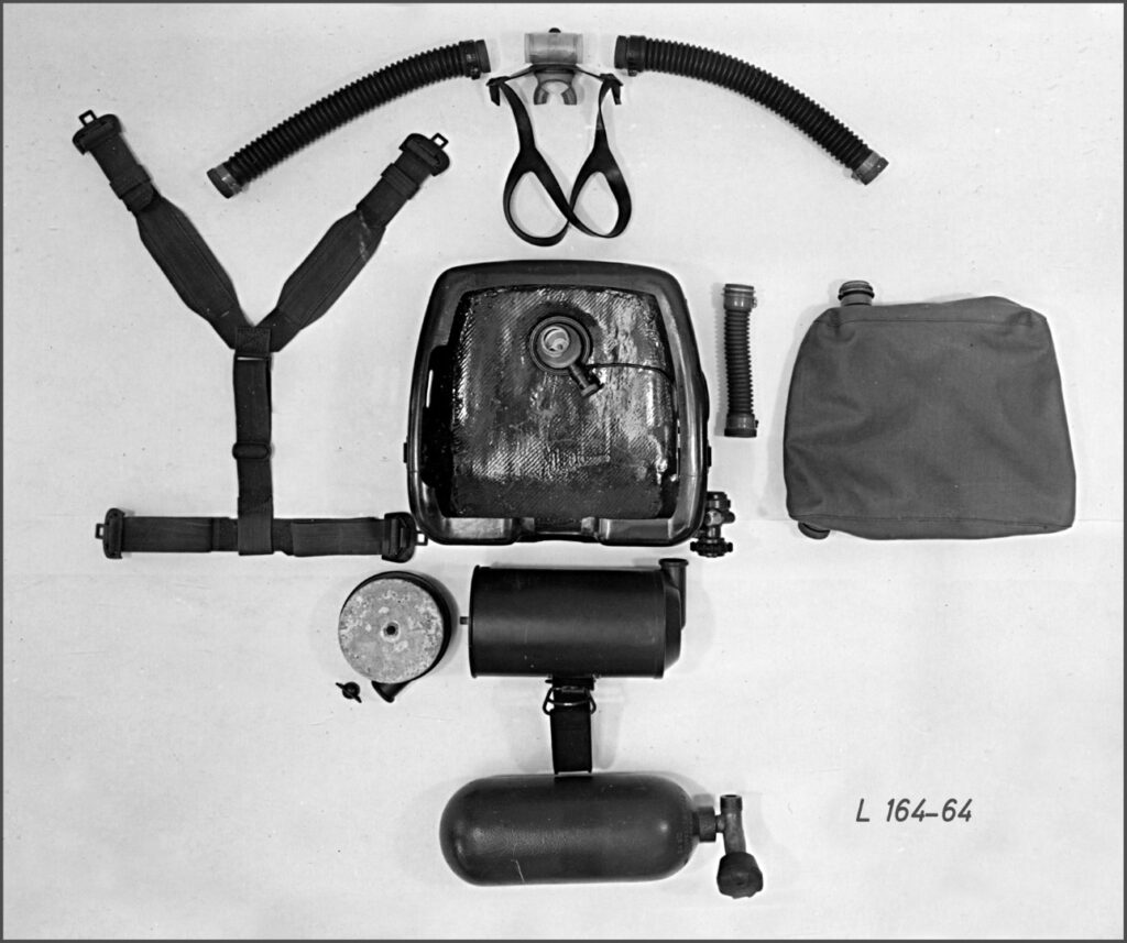
Image 21: LAR II, few components, manually interchangeable without tools. © Dräger Archive, Work recording No. L164-64
Page 8 of Part 3 of 4 (page 28)
The following devices were available: a) “LAR II,” older prototype model (old lung regulator without bypass) b) “LAR II,” improved prototype model (new bypass lung regulator) c) the French “Oxygers 57”.
Task: Physiological examination of the breathing gas during several hours of continuous load at a diving depth of 1 – 3 meters, comparing all three devices in multiple sessions over several days. The results were extensively documented.
Result: The improved “LAR II” prototype model had, even in comparison with the French Oxygers, the best respiratory physiological results. The technical construction met the requirements of the clients. The device was maintenance-friendly, and all components could be manually replaced in a short time.
From 1964 onwards, the Bundesmarine combat swimmers received the “LAR II” [Image 23]. Not everyone was enthusiastic. Ulrich W. Sassen, a former combat swimmer, recalls: “In the meantime, we had acquired some French ‘Oxygers’ devices ‘through informal channels.’ These devices were better and significantly lighter than the LAR II. Unfortunately, I had to give up the device, as the German gas regulations only allowed steel bottles for oxygen”14.
The “LAR II” was used by many naval units worldwide in the following years and proved reliable even in demanding conditions [Image 25]. It replaced devices such as the “Leutnant Lund II.”14
After conducting further physical measurement series, as well as tests in the pressure chamber under a maximum pressure equivalent to a 10-meter water depth with several test subjects and final trials in the Dräger swimming pool [Image 22] and in open water, the development was completed. The “LAR II” went into production at the end of 1964.
At Dräger, there was always a special duty of care and responsibility for the production of breathing apparatus. They were created with precision craftsmanship and were subject to ongoing technical inspections. Thus, the delivery of the initially ordered 100 units of the “LAR II” by the Federal Office of Defense Technology and Procurement was carried out gradually. According to the available sources, a total delivery time of 3 years was expected. It should not be forgotten that Department II of the Dräger plant was simultaneously working on various other constructions, including mixed gas and helmet diving technology.
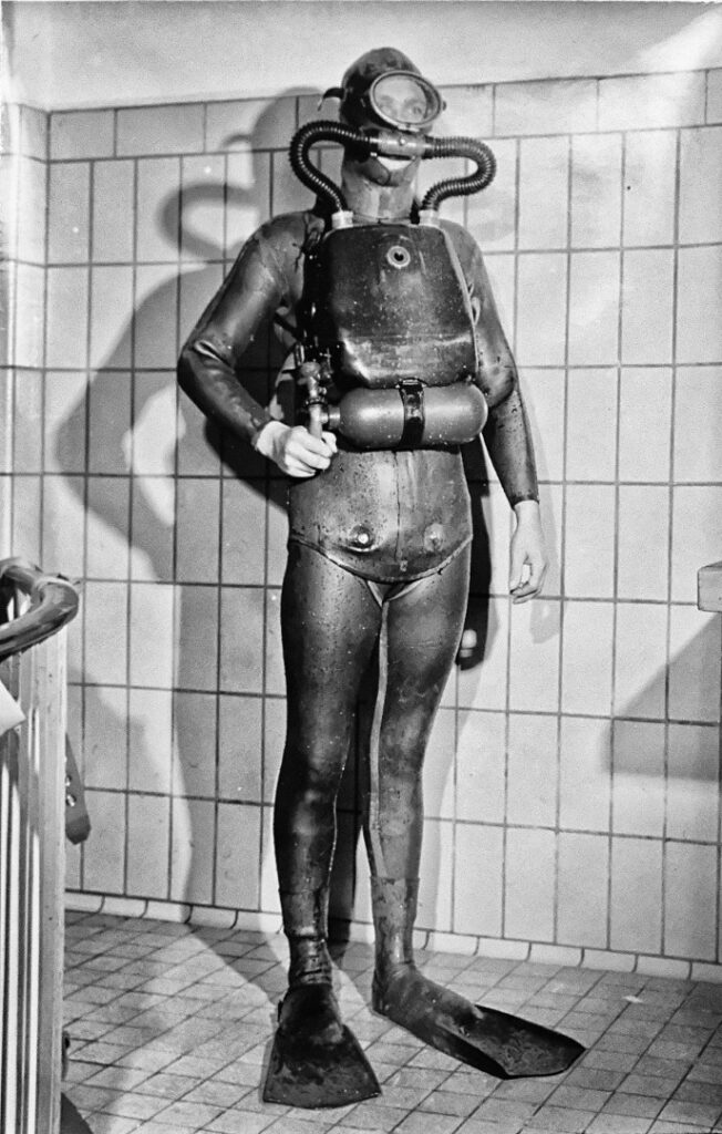
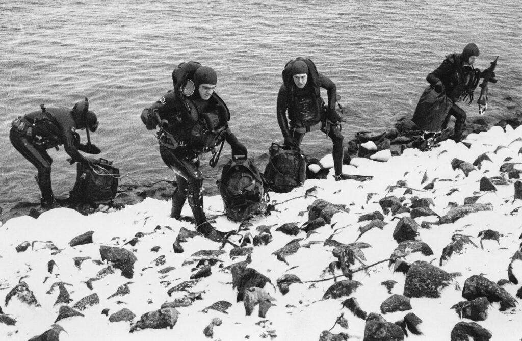
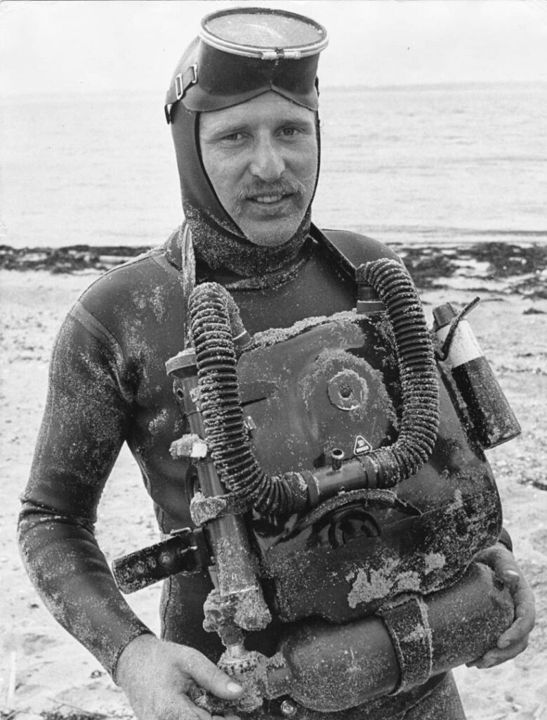
14 At that time, the German Compressed Gas Ordinance (now the Pressure Vessel Ordinance) did not yet permit the use of lightweight metal high-pressure cylinders in “portable breathing apparatus.”
Model LAR II A
“Even though the ‘LAR II’ proved its suitability for combat swimmer operations during the rough use of the following years, requests for improvements and changes were, as expected, not absent. A record of the discussion ‘Diving Equipment for Combat Divers’ at the Dräger plant in Lübeck in December 1967 shows that further development was already being pursued in 1965/66. In early 1967, the ‘LAR II A’ emerged as a successor proposal as a test device.”15
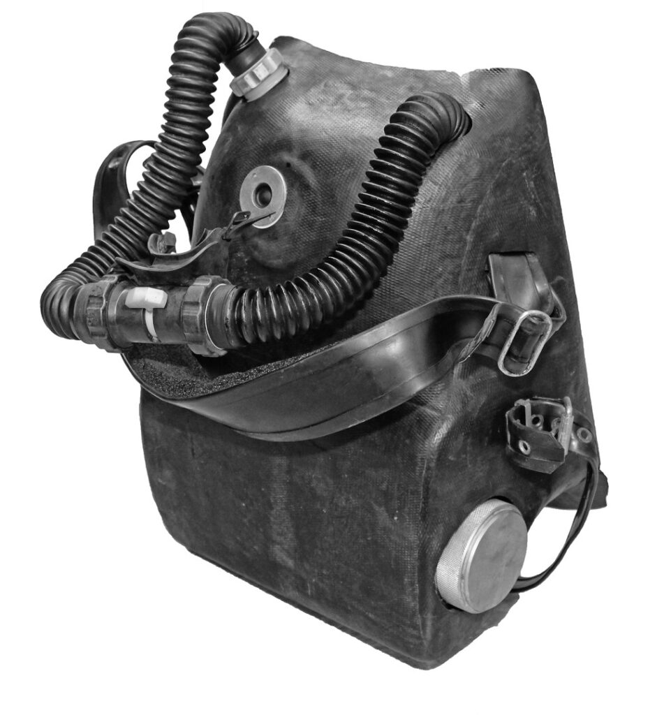
The basic principle corresponded to that of the “LAR II” with lung-automatic functionality and a bypass valve. One of the special features was the 2.5-liter lime container. Made of fiberglass-reinforced plastic with a rectangular cross-section [Image 27] and permanently placed in the lower part of the device housing. The round filling opening with screw cap was led out from the left side of the housing [Image 26] allowing for quick refilling from the outside without disassembly.
The rubber-coated housing extended into a wide, protruding rubber edge that was designed to fit the diver’s body—similar to the French “Oxygers 57” [Image 28]. When jumping into the water—from heights of up to about 10 meters—this prevented water from suddenly entering between the device and the body upon impact. The proper fit of the device was maintained. Additionally, the coating was noise-dampening and shock-absorbing.
The breathing bag was made of fabric coated on both sides with neoprene. Unlike the breathing bag of the “LAR II,” this material did not absorb moisture. The volume of the removable breathing bag was about 5 liters. The corrugated hoses were led into the device housing through round openings, eliminating additional screw connections. The screw fittings of the breathing hoses were made of plastic, unlike the “LAR II.” The relatively large lime container required the use of a smaller O2 bottle. The device was to be equipped with a 1-liter bottle / 300 bar, equivalent to 300 liters of usable oxygen. The military requirement of a 3-hour usage time was practically ensured with an average O2 consumption of 1.1 liters/min. It was essentially a successful design. Although the dimensions (HxWxD: 450x380x200 mm³, operational weight 10.8 kg) were roughly the same as the “LAR II,” it appeared larger. However, the “LAR IIA” did not meet the expectations for military use. The magnetic and acoustic measurements did not comply with the regulations of STANAG 1131 and 109716. The volume of the lime container was to be reduced to make the device smaller. Additionally, at that time, an O2 bottle could be filled to 300 bar at the Dräger plant but not at the Bundesmarine. As part of the ongoing development of a “LAR III,” this design was put on hold. It remained a prototype tested in open water as a single specimen.
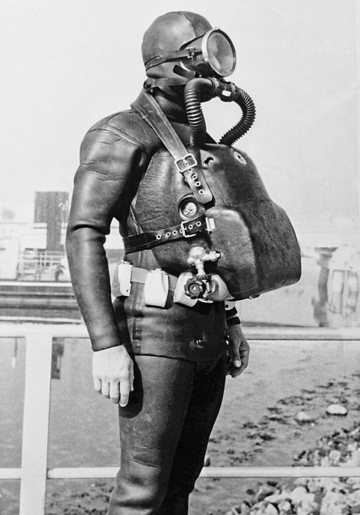
The KAR I
Combat swimmer device with constant oxygen dosing (order code T10198)
The collaboration between Drägerwerke and naval units of various NATO states continuously sparked special requests for the design of oxygen rebreather swim diving equipment, which were thoughtfully implemented by Dräger engineers. Thus, at the end of 1966, the model “KAR I” was created, a “constant-dose breathing regeneration device.”( konstantdosiertes Atemregenerationsgerät)
15 Test report “Test Site 71” AB Sea Small Combat Equipment, 13.12.1967 16 STANAG, abbreviation for “Standardization Agreement,” a standardization agreement among NATO member states on the application of standardized procedures and equipment.
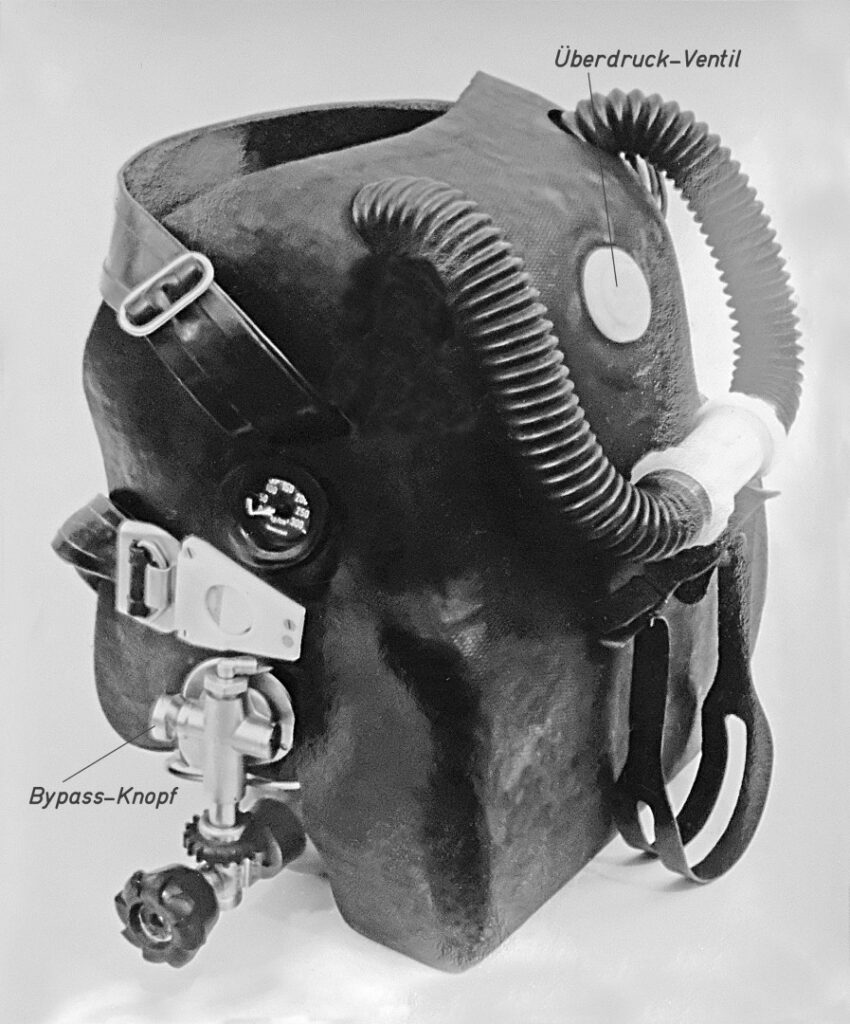
It does not technically belong to the series of lung-automatic “LAR” devices. However, since it was intended as a closed-circuit combat swimmer device, it is mentioned here. According to eyewitnesses17, the “Royal Netherlands Navy” was the client. A diving device for use up to a depth of 10 meters with an operational duration of about 3 hours (with the 1-liter O2 bottle / 300 bar also provided here).
Interestingly, we find here not only the same rubber-coated housing with the protruding rubber edge of the “LAR II A” but also the rectangular lime container with a capacity of about 2.5 liters and the 1-liter oxygen bottle. However, the lime container could be removed from the device for filling, as could the breathing bag with a capacity of about 5 liters.
The pressure reducer reduced the bottle pressure from 300 to about 3 bar and introduced a constant O2 flow of 0.9 liters/min into the breathing circuit. An additional pressure button provided a larger amount of oxygen when needed. An overpressure valve, which responded at a pressure of 15 cmH2O, allowed excess breathing gas to escape. It was embedded in the breathing bag and installed on the front of the device. A double breathing hose with a rotary valve mouthpiece formed the breathing circuit through the breathing bag and lime cartridge, as in the previously described rebreathers. The pressure gauge, built into the right side wall of the housing and readable from the outside, allowed for the checking of the oxygen supply.
The advantage of a constant-dose device construction lies in its (slightly) greater safety compared to lung-automatic dosing or manual metering. Closed lung-automatic oxygen rebreathers provide new oxygen via the regulator only after O2 consumption and consequently a decreasing breathing bag volume. If the breathing gas contains a high proportion of N2 due to insufficient or absent flushing with pure oxygen, the breathing bag volume does not decrease. The lung regulator is not activated, resulting in breathing without oxygen and consequently hypoxia, a particular danger point when using fully closed oxygen rebreathers.
In contrast, constant-dose rebreathers, like the “KAR I” described here, continuously supply oxygen. The risk of oxygen deficiency is comparatively reduced. However, this relative advantage of continuously flushing breathing gas into the circuit becomes a disadvantage during ascent and can only be limited by closing the cylinder valve. Otherwise, the increasing breathing bag volume escapes through the overpressure valve or at the corners of the mouth into open water. Experienced combat swimmers prevent this by timely exhalation of the circuit volume. Therefore, these devices do not always operate bubble-free and noiselessly. They are only of limited use for military purposes. Whether the “KAR I” remained a prototype or if more devices were produced has not been determined to date.
Dräger LAR II C
a special compact model
In accordance with the requirements of military clients, the production of a remarkably small LAR rebreather named “LAR II C” began in the late 1960s.
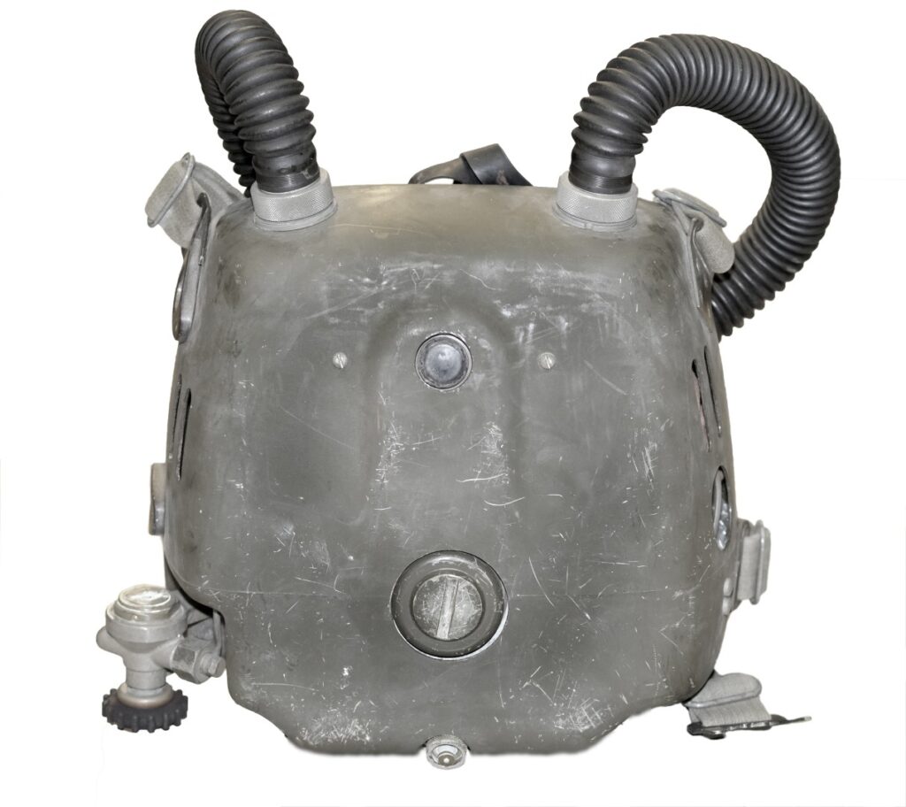
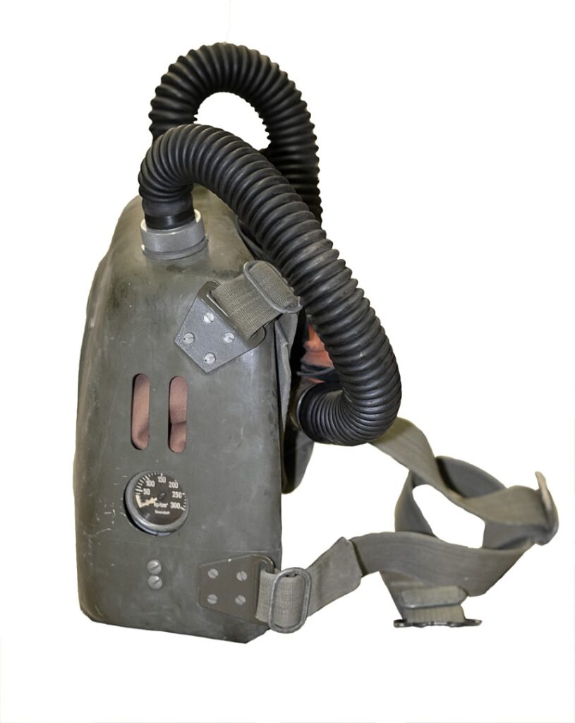
Investigations revealed18 that this space-saving version was intended for use from shallow-diving submarines for covert operations. In contrast to modern combat swimmer exits from contemporary submarines (e.g., the 212 A class, currently the most advanced in the German Navy) through a specially designed torpedo tube for four men with installed emergency breathing gas supply and a diameter of 72 cm or a lock in the tower, the passage through torpedo tubes at that time was somewhat less comfortable. For exiting, the divers passed through the “narrow tube” of 53.3 cm (21 inches) in diameter19 in a two-man team head to head with rebreathers on. For this method, as well as other confined spaces, such as passing net barriers in front of port facilities and other loopholes or caves, the “Dräger-LAR II,” although significantly smaller than the “LAR I,” was still relatively large. Thus, the technology of the “LAR II” was built into a small GFRP (Glass Fiber Reinforced Polymer) shell with even smaller dimensions than those of the later “Dräger-LAR V” [Image 32].
17 Dr. Ing. Wolfgang Lubitzsch, successor of Gerhard Haux, Drägerwerke Lübeck, conversations in 2019
18 Gerhard Haux, former chief engineer of Drägerwerke Lübeck, conversations in 2017 and 2018
19 The torpedo tube diameter of 21 inches corresponds to the standard NATO dimension.
The lung-automatic rebreather principle with a lockable valve mouthpiece was similar to that of the “LAR II.” However, a distinctive feature of this design was the (presumably first-time) use of an oval lime container in the O2 rebreather to achieve the smallest possible size [Image 33]. This permanently installed metal container with a fill volume of about 1.8 liters had a lateral filling opening accessible through a screw cap opening on the front side of the container housing [Image 30]. The bypass button of the lung regulator was located on the upper third of the housing. The non-removable breathing bag had a capacity of approximately 4.5 liters. A readable manometer was located on the left side of the housing, making it an interesting model overall.
The downside, however, was that filling and emptying the lime required shaking the entire rebreather due to the permanently installed lime container. The non-removable breathing bag made maintenance more difficult.
The device was a custom-made product. Detailed information about the clients and the number of units produced remains unknown to this day, as with most diving devices for military use.
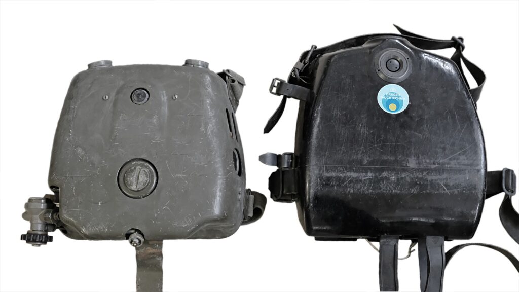
The Dräger LAR III
with adjustable inhalation resistance (order code T9400 + T9651)
Based on the successful model of the LAR II, Drägerwerke produced an almost identical rebreather in 1965 identical rebreather, but with a special feature, that was available from the beginning of 1966 – the “LAR III”.
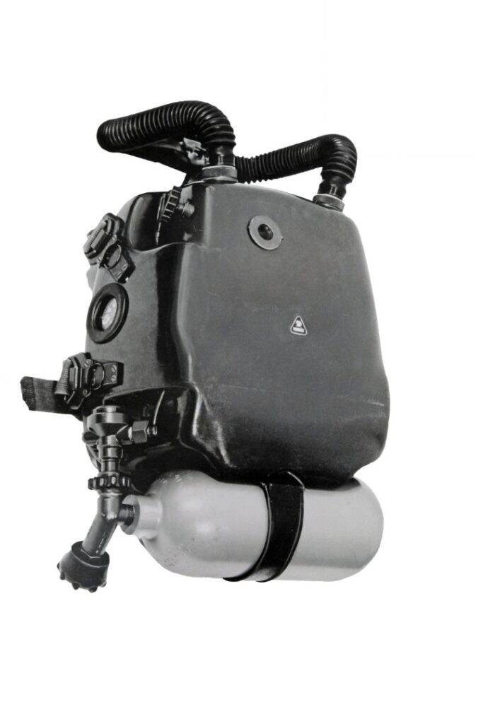
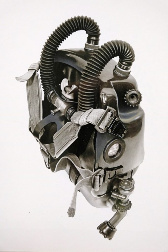
In contrast to the “LAR II,” where the response pressure of the lung regulator could only be adjusted outside of the water within certain limits using an adjustment screw, the “LAR III” allowed this adjustment individually underwater.
Each diver’s breathing technique and behavior are different. Several factors combine that are less significant in civilian diving but require respiratory physiologically appropriate diving systems in particularly strenuous military diving operations. Especially with sharply increasing breathing time volumes, an underwater unchangeable and limit-set lung regulator resistance can restrict the oxygen flow needed by the diver. Only pressing the auxiliary valve stops the restriction. Conversely, a response pressure set too lightly can lead to unwanted oxygen supply, which is also not desired in tactically critical situations. Additionally, according to the construction standards at that time, the opening resistance was still influenced by the decreasing pressure of the supplied oxygen.
The “Dräger-LAR III” was comfortable in this respect. By using a handwheel on the upper right side of the housing [Image 35], the response pressure could be continuously adjusted underwater between -10 and -30 cm H2O. It directly affected the spring tension of the lever valve in the lung regulator.
Structurally, unlike the “LAR II,” the lung regulator with the bypass button, which was also present here, moved slightly to the right from the centre of the housing. This naturally required a change in the breathing bag with correspondingly different connections.
The ability to adjust the response pressure underwater proved itself. Some of the Dräger-LAR models currently manufactured (e.g., “LAR 5010,” “LAR VII Combi A”) also have a handwheel for adjusting the inhalation resistance on the front of the device.
While the “LAR II” was still classified as “largely non-magnetic,” the “LAR III” received the official classification of a “non-magnetic design” (with measurement certificate) according to STANAG 1131 for the first time. This was made possible, among other things, by the use of a lightweight aluminium bottle (1.5 liters / 200 bar filling pressure). It was only noticed later that the brass pressure lines, as well as other components in the previous LAR models, had a relative magnetic permeability due to their nickel-plated surfaces, even if minimal. The nickel plating was replaced with non-magnetic surface coatings and materials.
The non-magnetic lime container made of a seawater-resistant aluminium alloy (AlMgSi) corresponded to the design of the “LAR II.”
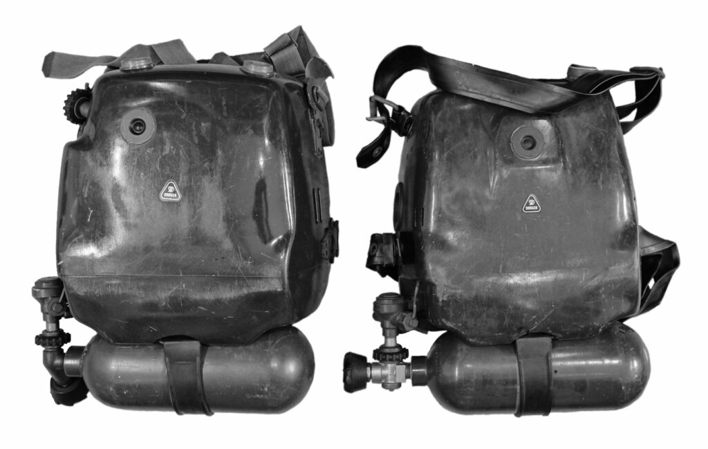
The maximum dive time was up to 3 hours at a maximum depth of 10 meters. The dimensions: HxWxD: 450x360x165 mm³, operational weight 9.7 kg (“LAR II” in comparison: HxWxD: 450x360x170 mm³, operational weight 11.5 kg). According to the available reports, the Royal Netherlands Navy also gave the first impulse for this “LAR III.” Alone from 1966 to 1973 (according to a list from Drägerwerke as a reference for gaining the US Navy as a customer), it was delivered to the following countries: 20
Greece 60 units
[Image 37], Turkey 40, Cyprus 20, Iran 40, Norway 10, Netherlands 50, Germany (FRG) 50, and the US Army 10 units, as well as “Special Forces” (n.a.).
According to the NAVXDIVINGU REPORT 11-74 (US NAVY EXPERIMENTAL DIVING UNIT), various military institutions of the US Navy tested the “LAR III” thoroughly between October 15, 1973, and April 1, 1974. It was compared to the “Lambertsen Emerson MK6 Rebreather” used by the US units up to that time. Even though the Navy SEALs initially had adjustment problems with the German rebreather (e.g., insufficient air delivery, no overpressure valve), the evaluation was positive. The extent to which this affected subsequent orders is unknown.
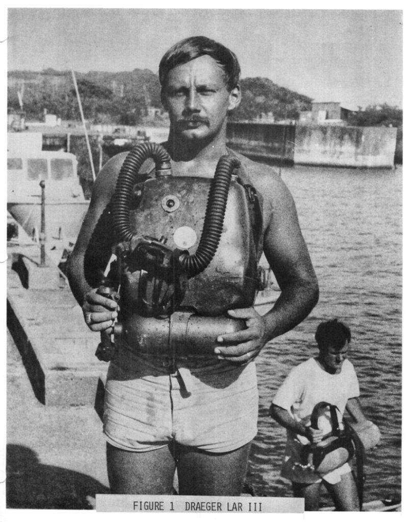
The “LAR III” was not a newly developed device, but an already field-tested rebreather as the “LAR II” with an additional functional adjustability of the inhalation resistance. It possessed high product maturity in its core functions. The solidly developed technology used in the device functioned flawlessly in military use by naval units. Nothing else was really expected.
Nevertheless, there was a popular complaint case at the time, which will be briefly described here. The aforementioned list of delivered nations ended with: “Special Forces” It is not excluded that this included the Yugoslav People’s Army. As reported earlier, Yugoslavia received US military aid starting in 1948 and was already equipped with the Dräger “Kleintauchgerät 138” from the USA at that time, as well as later with the model “Dräger-M 600”21 and the “Dräger-LAR III.” Although direct deliveries of these devices from Dräger to the Yugoslav People’s Army are not confirmed to this day, there was a lively contact between Lübeck and Split—for a special reason as well.
The Yugoslav Navy reported to Dräger at the beginning of the 1970s that life-threatening CO2 intoxications repeatedly occurred among combat swimmers using the “LAR III.” After the first search for causes, misuse during operations could be ruled out. Also, the examination of the technical condition and the monitoring of the correct operational preparation of the devices did not yield any convincing insights.
A working group of Yugoslav experts in diving medicine dealt with the problem. Comprehensive measurements in the laboratory and open water took place. The combat swimmers tested the “LAR III” diving devices under operational conditions in comparison with the “M600.” One of the measurement results is documented in [Image 39].
20 NAVXDIVINGU REPORT 11-74, Evaluation of the Dräger LAR III, May 5, 1974
21 Description of the “Dräger-M600” in the previous part of this article.
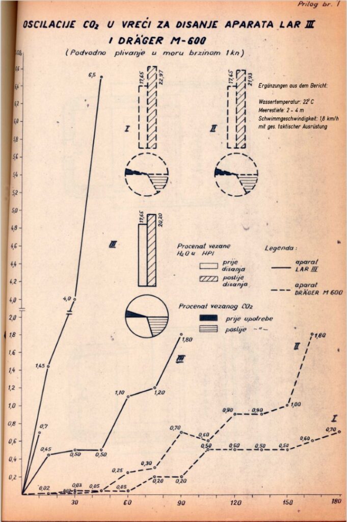
The final report from November 6 to 9, 197322 described the result. Significantly elevated CO2 concentrations were found, caused by wet and thus ineffective breathing lime. According to information from one of the Dräger engineers who went to Yugoslavia for the investigation (including Mr. Haux himself), about 350 cm³ of water was found in the lime container of the “LAR III” after a dive time of about 3 hours. The report of the Yugoslav investigative group concluded: “Water ingress due to insufficient sealing caused by uneven pressure of the lids on the canister opening and rapid wear.” Further laboratory measurements under stress on the subjects in the pressure chamber and under different temperatures “also showed a tendency for condensation to form in the lime container.”
Dräger took the incidents very seriously. They immediately conducted a review and revision. The findings of the Yugoslav investigative group’s report were confirmed after examination by Dräger. The rubber seals of the lime container lids could no longer ensure a secure closure due to severe wear. Timely replacement could have certainly prevented the disaster. Additionally, a negative pressure in the breathing circuit with high inhalation resistance settings, water ingress through a leak would only be facilitated. Additionally, the Dräger engineers pointed out that the formation of condensation in the metal lime container is not a defect, but characteristic in the presence of large temperature differences. The lime container of the “LAR III” (and the identical “LAR II”) also did not have an effective water trap.
The Yugoslav Navy was also aware that the comparison with the “Dräger M600” [Image 39] could only be academic in nature. The aluminium lime container of the “LAR III” was surrounded by cold free water. The brass lime container of the “M 600” was warmed by the exhalation air in the breathing bag. Additionally, the “Dräger M600” had a lime container with a capacity of 3.8 liters compared to the 2-liter lime container of the “LAR III”. Small cause, big effect—the error was corrected.
The Yugoslav Navy continued to use the “LAR III” (alongside Russian rebreathers) without difficulties after the revisions. Even before this incident, work on a successor model considering all the gathered experiences had already begun. Dräger was already testing the “LAR IV” and brought the completely newly designed “LAR V” to the market two years later (which was then also equipped to the Yugoslav Navy, among others). More on this in the next part of this article.
Additionally, my heartfelt thanks to: Dr. Wataru Kähler, Maritime Medical Institute of the Navy, Kiel, as well as the former Swimming-divers of the German Navy, Gerhard Scherer, Wolfram Giebel, and Jochen Gerlach.
All images in this article with the captions “© Dräger Archive” are the property of Drägerwerk AG & Co. KGaA, Lübeck. All rights reserved. Captions HK = Helmut Knüfermann
22 IZVJEŠTAJ O FIZIOLOŠKO–TEHNIČKIM ISPITIVANJIMA APARATA LAR III (REPORT ON PHYSIOLOGICAL AND TECHNICAL INVESTIGATIONS OF LAR III DEVICES)
s1
s2
s3
s4
PART 4
Page 1 of Part 4 of 4 (page 34)
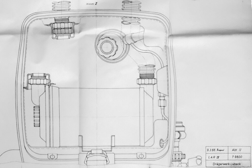
“Dräger diving equipment for Combat Swimmers”
Chronological development of closed-circuit oxygen rebreathers by Dräger for military underwater use | Part IV, devices in “hard-shell” design
By Helmut Knüfermann
The oxygen rebreather LAR IV
Paradoxically, it was Gerhard Haux who wrote in 20021: “Why there was never a LAR IV is still beyond me today.” The engineers of Division II at that time and documents from 1969 helped to shed light on this mystery.
Sufficient experience with the (described in the previous part of this article series) LAR II, LAR II A, and LAR III led to the further development of this rebreather series. The primary goals of the redesign were:
- longer service life,
- lighter weight,
- lower breathing resistance, and
- reduced size.
As early as 1966, the first drawings were created as a draft for a “LAR IV” [Image 01], which unmistakably also contained elements of the “LAR IIA” and “LAR III” – such as the housing with protruding the edge and the handwheel for the adjustable response pressure of the lung regulator. However, this was only a preliminary draft, which did not progress beyond the idea and planning stages.
It was not until 2 years later that a “LAR IV” left the Dräger experimental workshop, starting in April 1969 to prove its suitability for swimming divers [Image 02]. The Testing Center 71 of the German Federal Armed Forces in Eckernförde provided this first test model, loaned by Dräger, to test divers of the swimming diver company.
THE DESIGN
For longer usage duration even with high gas throughputs, this device received a cylindrical lime container with a capacity of 2.5 liters, which is 0.5 liters larger than the comparable “LAR II or III.” With moderate load and an oxygen consumption of 1.1 liters per minute, the “LAR IV” enabled a usage time of approximately 203 minutes (3:20 hours), including flushing and residual pressure2.
The first-time use of the lime container material GRP (glass-reinforced plastic)3 for Dräger O2 rebreathers resulted in weight savings and reduced condensation formation.
1– Gerhard Haux, until August 1977 Chief Engineer of the Dräger Diving Technology Department, in his book: “Typical Haux,” Haux Publishing 2002
2– based on the then Dräger breathing lime with 80 liters CO2 absorption capacity per kg
3– GFK = Glass fiber reinforced plastic (GRP) or fiber-reinforced plastic (FRP)
Page 2 of Part 4 of 4 (page 35)
The oxygen supply of a 1.5-liter aluminium bottle at 200 bar filling pressure ensured a capacity of 300 liters, providing the necessary supply for the mentioned usage time. The maximum diving depth was, as with all closed LAR O2 rebreathers, limited to 10 meters.
The “LAR IV” featured separate breathing bags as a special characteristic. In the brief description of the device from January 1969, it states: “The breathing bag is designed as separate inhalation and exhalation bags. The breathing bags are made of stretch fabric coated on both sides with a neoprene-NK mixture. The movable volume is approximately 4.3 liters.” The positive experiences with Dräger mixed-gas devices (SMS, FGT, etc.), whose separate breathing bags resulted in reduced breathing resistance, should also be advantageous for this military tactical diving device.
Another factor was considered in the selection of two instead of one breathing bag:
According to laboratory experiments, the flow velocity of the exhalation volume through a lime container located between two breathing bags is slower than a direct and forced exhalation through the lime4. This results in a slightly longer retention time of the breathing gas in the container for more effective CO2 absorption.
Although both breathing bags worked physiologically separate, they were arranged side by side and sewn together in the middle [Image 03]. This double breathing bag was guided over the lime container down to the lower edge of the device housing and could be fixed there using fastening buttons.
The pressure reducer adopted from the “LAR II” also received a movable attachment to the device housing here. The connection between the O2 bottle and the pressure reducer could thus be securely closed without the use of tools and correspondingly easy to loosen.
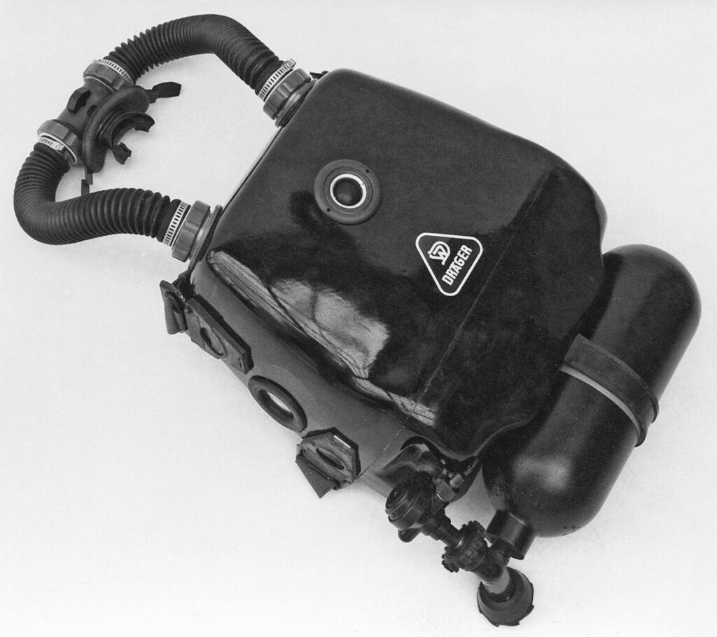
Initially, a new plastic housing for the lung regulator was considered for the “LAR IV,” but eventually the lung regulator with an additional valve (bypass) from the “LAR II” was adopted. However, it was planned to equip it with a new, more resistant membrane, as the previous membrane in the “LAR II” tended to wear out quickly. For a largely non-magnetic design, the “LAR IV” omitted chrome plating on the lung regulator. The adjustability of the lung regulator’s response pressure outside the water with an Allen key between -10 and -30 cm WS was retained. The breathing hoses, fastened with non-magnetic metal hose clamps to the connection nozzles, matched in length, diameter, and flexibility to those of the “LAR II.” The mouthpiece and device-side connection fittings were made of a high-quality polymer. The rotary slide mouthpiece was significantly smoother than that of the “LAR II” due to a new, more suitable plastic. Red and green markings (port and starboard) on the valve housing ensured correct assembly.
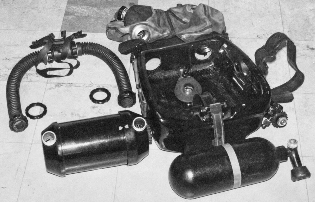
As with previous LAR designs, the pressure gauge was embedded in the side wall of the housing and could not be monitored by the device carrier themselves during the dive. It was assumed that swimming divers generally operated in pairs, allowing mutual control of the oxygen supply. Even though the possibility was discussed at that time that swimming divers could be used as solo divers in an emergency, and the installation of the pressure gauge in the upper housing wall between both breathing hoses would be more practical…
4– der Dudelsack-Effekt The “bagpipe effect” (Dudelsack-Effect).
Page 3 of Part 4 of 4 (page 36)
for this device, the positioning was in the side (right) housing wall. Small changes, such as a more convenient angle for the valve handwheel, a revised version of the quick-release buckles on the shoulder straps, and a diver emergency signal holder, complemented the design of the “LAR IV.”
In the construction of the housing itself, the original idea of the protruding edge (as described in the “LAR IIA” — see the first draft drawing [Image 01]) was abandoned, and the housing was completely redesigned to accommodate the space requirements for double breathing bags, a larger lime container, and larger and more stable quick-release buckles.
Ultimately, measurements showed that the test model of this new “LAR IV” was 10 mm longer and 20 mm wider than the “LAR II,” but also 900 g lighter due to the inclusion of a plastic lime container.
Testing in the laboratory and open water
Dräger engineers first tested the finished “LAR IV” themselves at the Dräger factory under laboratory conditions and in the Dräger-owned swimming pool [Image 04]. At that time, a cooling unit for the 9-meter-long and 2-meter-deep pool was not available. To also test rebreathers at low water temperatures, the pool was filled overnight with a corresponding amount of dry ice to cool it down to about 3 to 4°C.
Subsequently, from April to August 1969, the device was tested in the laboratory, in the climatic chamber of WTD 715, and during dives in the Eckernförde Bay.
The service life of the breathing lime under different volume/flow conditions and CO2 concentrations, as well as at low temperatures (air 10°C, water 1.5°C, 12 hours), and the examination of the technical specifications according to the requirements specification provided the first laboratory results.
This was followed by dives with “normal divers” (combat swimmers) in Eckernförde Bay, compared with the “LAR II” [Image 05].
The magnetic measurement took place at the measurement site of Erprst 726. The acoustic measurement was carried out in Aschau, at the specially established lake measurement site of WTD 71 in the military restricted area, south of Eckernförde.
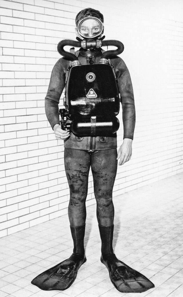
5– Wehrtechnische Dienststelle 71 of the German Federal Armed Forces, Eckernförde
6– Testing Center 72 for magnetic ship protection of the German Federal Armed Forces, Kiel-Friedrichsort
Page 4 of Part 4 of 4 (page 37)
Final Report and Conclusion of the Testing of the LAR IV
The device passed the respiratory physiological test excellently. The breathing resistance was pleasantly low due to the separate breathing bags. The functional testing of the device at low temperatures by a diver in -1.5°C cold seawater container at -10°C air temperature and ice formation on the water surface also ended with positive results7. After surfacing, despite the spontaneous air freezing of the device, it was possible to breathe from it without any issues. The volume of lime and the size of the breathing bags were satisfactory and met expectations. However, the test report of WTD 71 demanded various modifications.
The technical closure of the lime container lid needed revision because lime could fall into the central axis’ nut thread during the filling process. Although the lung regulator adopted from the “LAR II” worked flawlessly, the desired membrane reinforcement, as specified in the requirements document, could not be detected. The fastening buttons of the breathing bag were poorly accessible. Particularly, the screw connection of the breathing bag with the breathing hoses was cumbersome because a connection with the device housing had to be made simultaneously. The installation of the pressure gauge in the upper housing wall between both breathing hoses was now required. The quick-release buckles of the shoulder straps, which already tended to fatigue the inner spring in the “LAR II” and particularly lost their effectiveness due to the ingress of sand, should be replaced with simple thorn buckles. Furthermore, the quick-release buckles could open under sudden stress (jumping off the pier, running with the device on land), causing the device to detach from the carrier. The position of the angled bottle valve handwheel pressed into the groin area. A straight valve was necessary. Lastly, a holder for the emergency signal should be installed.
Ultimately, however, the “LAR IV” diving device did not meet the STANAG 11318 requirements for maintaining non-magnetic properties. It was concluded that “the test model, compared to the introduced device LAR II, does not show any significant improvements.”
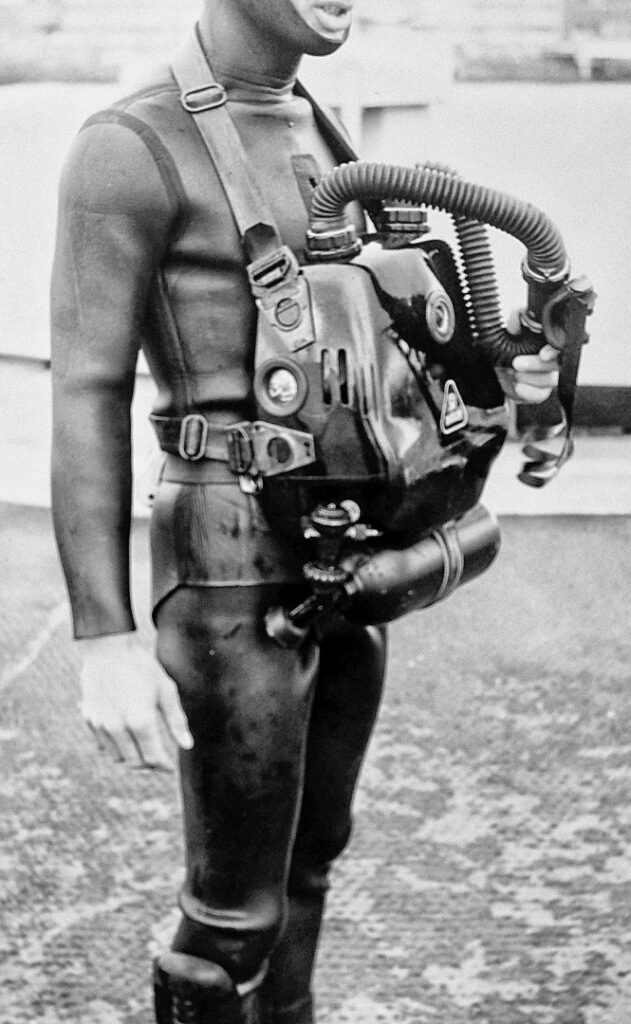
7 –Temperature readings from the final report of WTD71
8– STANAG, abbreviation for “Standardization Agreement,” a standardization agreement of the NATO member states on the application of standardized procedures and equipment.
Page 5 of Part 4 of 4 (page 38)
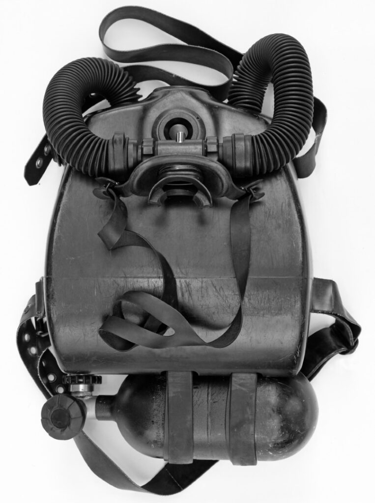
A meeting with the engineers of the Dräger works in September 1969 resulted in the conclusion that the modifications were indeed feasible. However, the total number of requested changes ultimately exceeded a reasonable effort. It was decided to rethink the entire design. The test model, which was loaned by the Dräger works to WTD 71, was promptly returned. The testing contract was financially closed by BWB9 by the end of 1969. Therefore, an oxygen rebreather Dräger model “LAR IV” existed, but only as a single prototype.
The oxygen rebreather model “LAR V” T12700
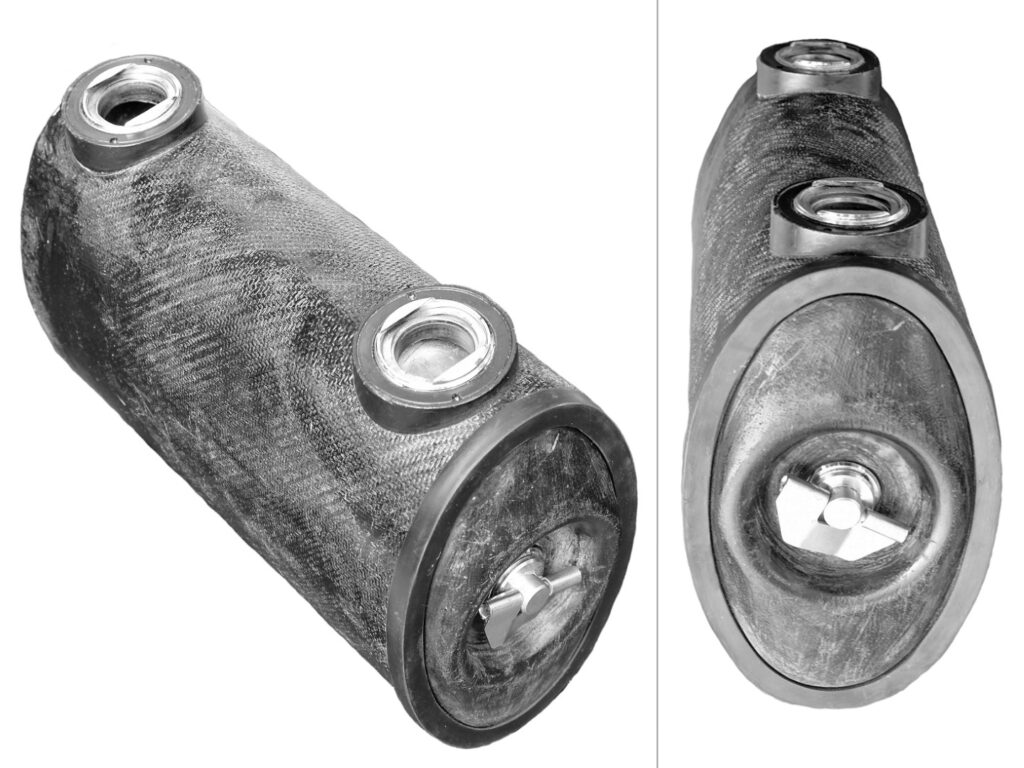
Although the engineers at Dräger works invested many ideas and several years of development work into the “LAR IV,” saying farewell to this project was not a loss. Valuable insights and experiences contributed to a fundamental new development—the oxygen rebreather “LAR V” [Image 06]. A smaller and lighter design with longer usage time and lower breathing resistance compared to the “LAR II,” which had been successfully used for 10 years, was, as demanded for the “LAR IV,” the primary design goal.
Special attention was given to the redesign of an oval lime container. The previously positive experience with oval lime containers for Dräger rescue equipment10 likely served as a model for achieving the flattest possible device design [Image 07]. To achieve good mechanical strength, the container was made of solid glass fiber reinforced polyester with a 5 mm wall thickness using the “hand lay-up” method.
Approximately 2.5 liters of breathing lime (as opposed to the 2-liter container of the “LAR II”) ensured adequate CO2 absorption for a usage time of more than 3 hours. A water trap on the right side of the lime container served as a moisture catcher and held about 200 cm³ of water [Image 08]. A more sensitive response of the lung regulator compared to the “LAR II” was achieved through a new (and less maintenance-prone) membrane with a larger effective area in a slightly modified housing design. A series of trials with elastomers, from fabric-reinforced polyamides through various rubber types to silicone mixtures, finally led to a thermally, chemically, and technically highly durable regulating membrane [Image 09].
9– BWB stands for Bundesamt für Wehrtechnik und Beschaffung (Federal Office of Defense Technology and Procurement).
10– “Construction Principles for Lime Cartridges in Breathing Apparatuses” by A. Pasternack, Dräger Journal 340
Page 6 of Part 4 of 4 (page 39)
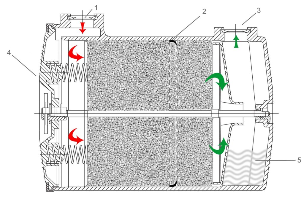
1:Exhalation side (red)
2. Rubber lip to prevent channeling (CO2 breakthrough)
3.Inhalation side (green)
4.Enclosure with spring pressure
5. Watertrap
The possibility of stepless adjustment of the response pressure between -10 and -30 cm WS using an Allen key, as well as the bypass function, were also retained here. A lockable rotary slide mouthpiece, made entirely of a light and robust polymer with a large inner diameter and newly designed valves, provided the expected lower breathing resistance [Image 10].
Environmental and breathing pressure changes place high demands on the dynamic properties of an automatic breathing apparatus. The “LAR V” therefore also received a new pressure reducer (Dräger No.: T 11791). It was membrane-controlled “compensated” according to the surrounding water pressure
[Image 11]. The lung regulator always received a proportionally adjusted intermediate pressure (today’s diving regulators are mostly pressure compensated). The result was a more balanced “breathing comfort” with fewer fluctuations11.
To counter the risk of freezing, this cold water-compatible pressure reducer was also equipped with an overpressure valve [Image 11, Pos. 11]. The valve was connected to the intermediate pressure and could be set to an overpressure of about 7 – 11 bar. This prevented breathing gas from flowing into the breathing bag in case of freezing.
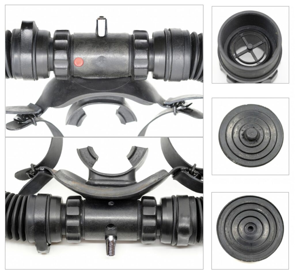
11– The respiratory physiological difference between compensated and non-compensated first stages in pure oxygen rebreathers up to a maximum depth of 10 meters is, according to my own experiences, minimal.
Page 7 of Part 4 of 4 (page 40)
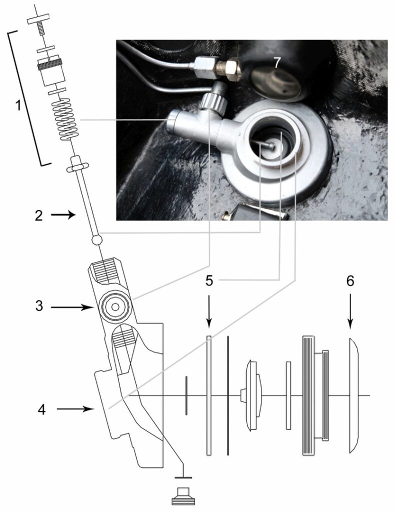
Top and bottom view, as well as valve seat with valve disc (front and back)
- Spring-loaded lever guide with response pressure adjustment
- Lever
- Intermediate pressure connection
- Screw thread
- Rubber membrane
- Breathing bag connection
- Bypass rubber button (front side of the device)
- Included in the image: back side of the pressure gauge
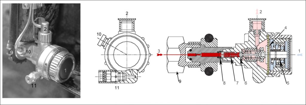
Original drawing edited by HK
- Ambient pressure
- Intermediate pressure outlet
- High pressure
- Membrane
- Adjusting spring of the water chamber
- Valve cone
- Closing spring
- Sinter filter
- Handwheel
- High pressure connection for pressure gauge
- Overpressure valve
Page 8 of Part 4 of 4 (page 41)
The “LAR V” received a single breathing bag for inhalation and exhalation with a volume of approximately 6.5 liters made from textile fabric coated with rubber on both sides (the inner rubber coating being stronger than the outer one) [Image 12]. Connections for the lung regulator and inhalation hose made of plastic, as well as a metal bayonet connection for the lime container, were positioned in the breathing bag at their respective connection points [Image 13]. All connections were secured with cotton threads – a typical and reliable “Dräger variant”. The two inlets for the inhalation hose and lung regulator in the bag were connected by a spiral spring, about 2.5 cm wide, to prevent the breathing bag from collapsing.
Eventually, all components – except the pressure reducer and breathing hoses with rotary slide valve mouthpiece – found their place in a newly designed GFK housing [Image 14]. Compared to the previous “LAR II,” the device was smaller and slimmer, but when ready for use, it weighed no less than 11.5 kg [Image 15].
During the discussions ignited by the construction of the “LAR IV” regarding the correct position of the pressure gauge, it was decided after consultations with experienced swimming divers to install it in the upper housing side [Image 16]. This allowed the device carrier to check the bottle pressure themselves during diving. Especially in emergencies, a companion may not always be available to read the pressure gauge from the side of the housing (as in the devices “LAR II and III”). The maximum allowable bottle pressure of 200 bar and the lower pressure range of 0 – 25 bar were marked with luminous paint.
A larger diameter of the openings in the breathing circuit compared to the “LAR II”, from the rotary slide valve mouthpiece through the corrugated hoses to the connections, resulted in lower breathing resistance.
One of the most important required properties of an oxygen rebreather for combat swimmers is maximum “stealth.” Great importance was therefore attached to acoustic and magnetic latency in this new design.
Unlike the side-mounted gauges in the “LAR II and III,” the user here could easily check the bottle pressure themselves.
By the early 1970s, the digitization and processing of analog received sound signals (A/D converters) marked significant progress. It became possible to use the slowly available computer technology for the signal processing of sonar systems. Combined group listening systems enabled the reception of direction and strength of the digitized reception signal in the desired frequency range. The unnoticed approach of combat swimmers underwater to military units and facilities became increasingly difficult. Passive multistatic detection systems with bearing angle determination and frequency analysis could already filter out an approaching opponent from the background noise at great distances.
The lung regulator of the “LAR II” was primarily the source of telltale sound waves. The cyclical hissing of the flowing oxygen through the lever valve of the 2nd stage into the breathing bag, as well as the activation of the bypass valve, caused a far audible and typical sound pattern underwater [Image 17]. The new construction of the lung regulator of the “LAR V” with revised valves
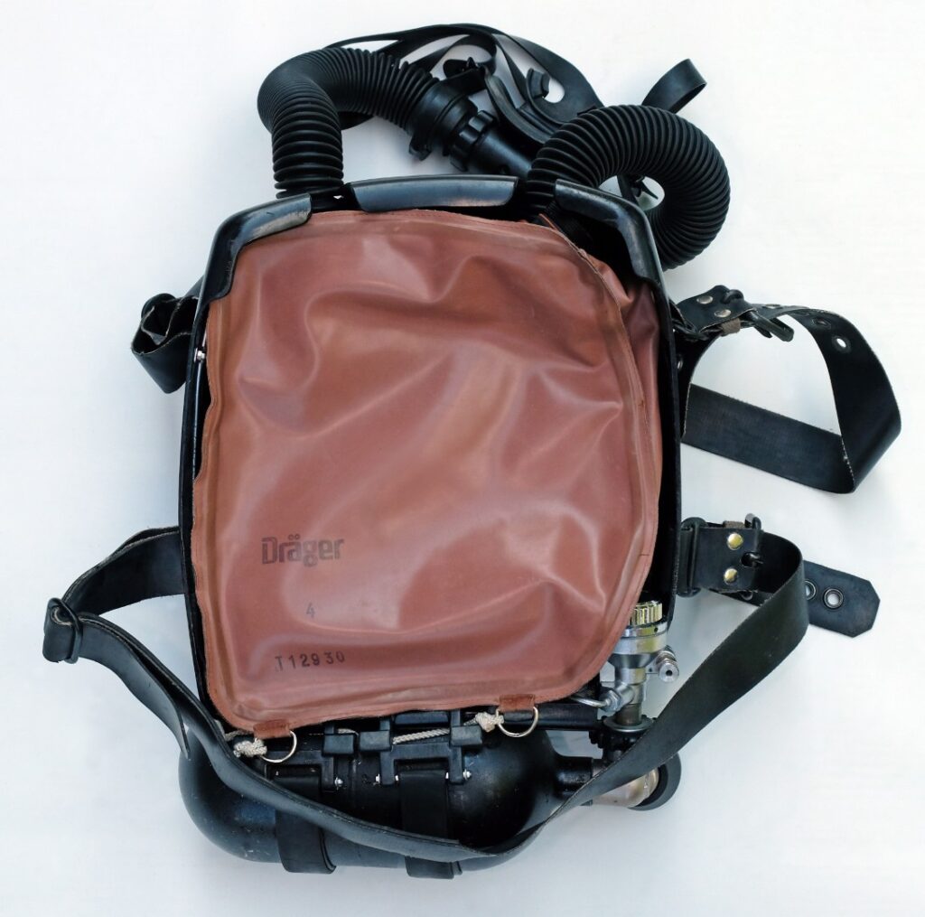
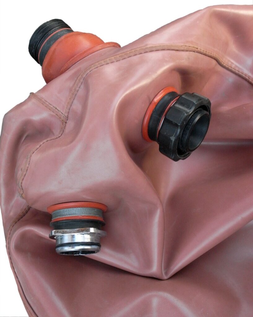
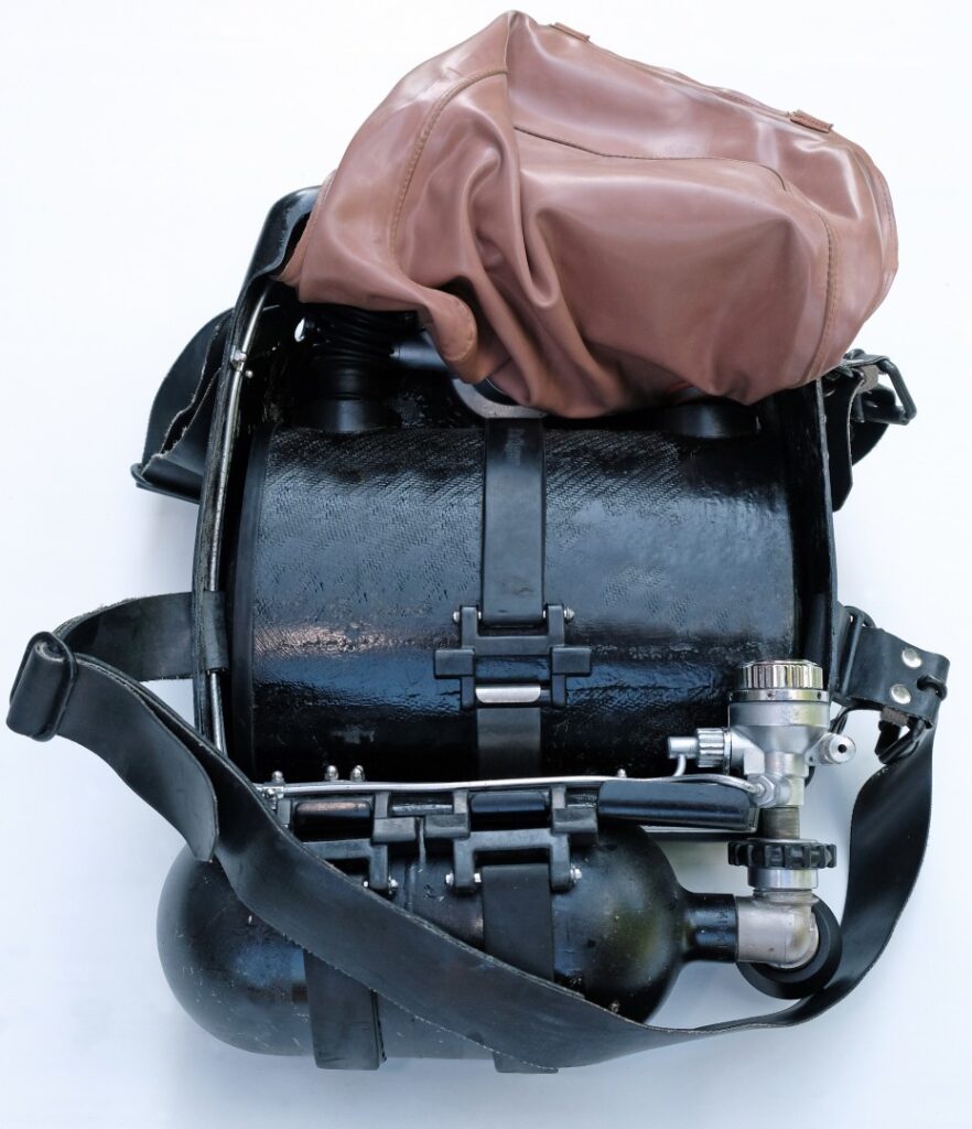
Page 9 of Part 4 of 4 (page 42)
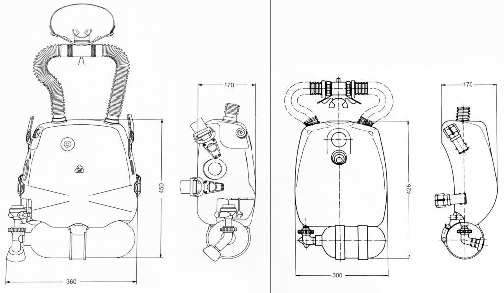
(Disc and valve seat) contributed to reducing turbulence and noise 12. The previously mentioned larger membrane with more sensitive response behavior also helped [Image 09]. Regarding noise development, the previous directional valves of the “LAR II” in the mouthpiece also caused problems. Unfavorable breathing flow speeds led to a hydro-acoustically measurable “fluttering”. The so-called “flutter valve”
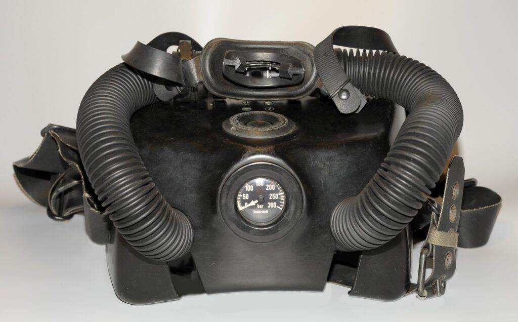
© Photo: HK
…rightfully earned its name here. For the “LAR V,” the valve discs, including the valve insert, were redesigned with the result of a continuous laminar flow over a wide flow range, preventing unwanted valve disc oscillations [Image 10].
The use of closed-circuit oxygen rebreathers for combat swimmers might lead to the assumption that they generally have a non-magnetic (AMAG) build. However, practice shows that the tactical equipment carried (weapons, mines, reconnaissance, and transport means) due to its magnetic conductivity nullifies the advantage of a non-magnetic diving device. Therefore, the “LAR V” was usually delivered with a 1.5-liter O2 bottle made of ferromagnetic steel (with hand valve, pressure reducer connection R 3/4″, operating pressure: 200 bar to 10 bar).
Special combat swimmer missions in mine-laden areas (or also secured military objects with magnetic loop induction) still require non-magnetic rebreathers.
Ground mines with magnetic ignition were not only laid in both World Wars but are still used today in consideration of current hotspots in crisis areas as mine barriers also in shallow waters. The passage of these areas by combat swimmers for strategic, operational, and tactical reconnaissance always bears the risk of activation and detonation of a magnetic mine (up to 900…
12– Today’s devices contain sinter filters in the lever valve to reduce noise.
Page 10 of Part 4 of 4 (page 43)
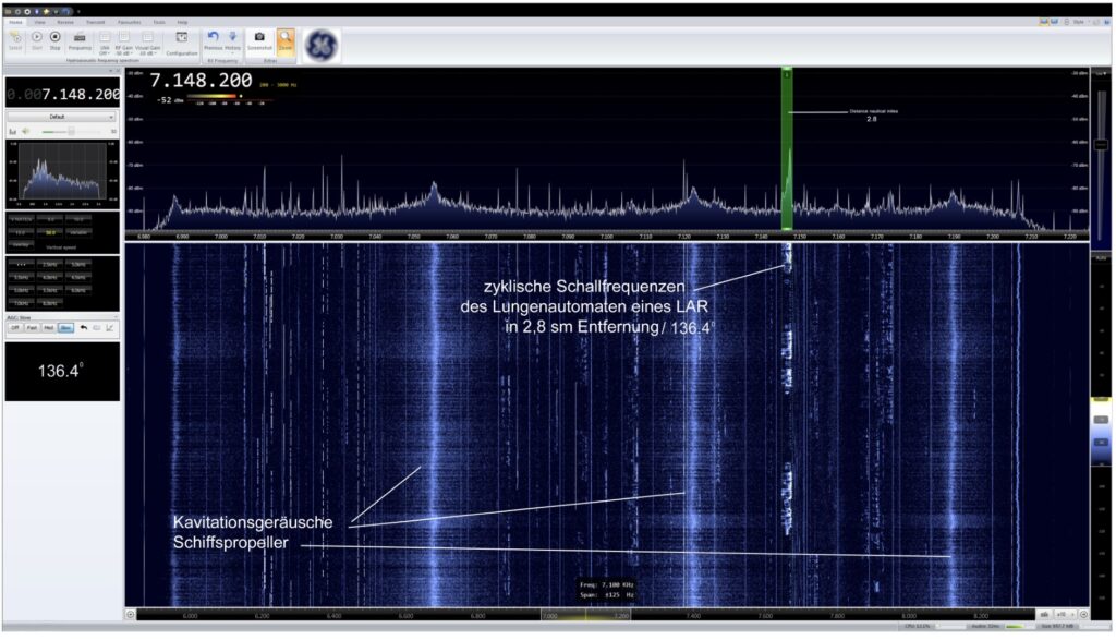
The sensitivity of this type of sea mine is extremely high. The mine measures the disturbance of the natural surrounding magnetic field13. Magnetic field changes due to magnetic anomalies can already lead to the triggering decision in the pT (picoTesla) range.
Therefore, a non-magnetic version of the LAR V was available. The magnetic signature of all components was reduced to “near zero.” Compared to the “LAR II,” a number of plastics were used for the “LAR V,” which did not raise the question of non-magnetic properties. Chrome-plated elements were omitted. It is not so much the chrome layer itself but more the intermediate layer of copper or nickel that is ferromagnetic.
The oxygen bottle was of particular importance. Non-magnetic aluminium as a pressure vessel was initially considered but was ruled out due to its more voluminous size compared to steel with the same content.
Dräger decided to use non-magnetic oxygen bottles with a capacity of 1.5 liters for the “LAR family” made of submarine steel – a special steel alloyed with manganese and molybdenum14. The (austenitic) structure is stabilized here, and the formation of ferrite is avoided. An O2 pressure bottle manufactured in this way is of the highest non-magnetic quality and can no longer be located by the distortion of an external magnetic field. It is also highly crack-resistant, extremely rust-resistant, militarily robust, but also heavy and expensive [Image 18].
The Test Facility 72 for Magnetic Ship Protection tested the non-magnetic properties of the entire device after the completion of the “LAR V” through artificial magnetization and then determined the residual susceptibility, one of the basic conditions for approval for series production.
This was followed by intensive testing in the Dräger test department and Dräger’s own swimming pool. Werner Sartor, a development engineer responsible for the design of the O2 closed-circuit diving devices in Department II of the Dräger works from 1965 to 1976, reported one of his “LAR V” test dives. He managed a continuous 6-hour dive at 4°C (cooled) water temperature with a single fill of breathing lime (under resting breathing conditions), a peak performance that was probably rarely achieved even by combat swimmers later on. This was also proof of a technically advanced and reliable closed-circuit device.
After subsequent testing at WTD 71 in Eckernförde and by combat swimmers of the German Navy, the “LAR V” went into series production in 1975. It became one of the most widely used devices by many naval units worldwide [Image 19].
Only in 1997, after 22 years of successful military use, did Dräger cease production of the “LAR V” to introduce subsequent models. Even today (2019), combat swimmers regret the discontinuation of the small and uncomplicated “LAR V”15 [Image 20].
13– In Central Europe, the strength of the natural magnetic field (magnetic flux density) is approximately 50 µT (micro-Tesla)
14– Submarine steel (X 2 Cr Ni Mn Mo N Nb 23-17-6-3) Tensile strength 800-1050 N/mm²
15– Jens Höner, Combat Swimmer of the German Navy
Page 11 of Part 4 of 4 (page 44)
Over the years, the “LAR V” also received various small modifications at Dräger. These devices, however, are not listed here. It is necessary to differentiate between Dräger’s own additions and later external modifications.
In the early 1980s, Dräger delivered its first “LAR V” devices to US military customers in the USA16. These received some modifications, including slight housing changes, and were designated as “LAR V Mod 0 UBA”17 Type “MK25.”
At the beginning of the 90s, the US military ordered a device with a low magnetic signature. Jointly with Drägerwerke in Lübeck, the “LAR V Mod 1 UBA” was developed with aluminium bottles of 1.9 liters capacity (390 liters O2) at 3000 psi (207 bar) filling pressure. Revised breathing valves with further reduced breathing resistance were also part of the redesign.
A “LAR V Mod 2 UBA,” with a larger lime supply and neoprene insulation of the lime container for thermal insulation, followed as the next addition. It allowed for longer dive durations at low temperatures.
The “LAR V” manufactured by Dräger embodied high-priced top technology. Even spare parts were not exactly inexpensive. To save on procurement and maintenance costs, the devices in the USA received their own pressure reducer. This affordable “oxygen regulator” was based on a simple piston construction and was not pressure compensated. The overpressure valve of this pressure reducer was fixed and not adjustable.
Other parts also fell victim to cost-cutting. The breathing bag was replaced with a slightly larger polymer bag with urethane coating (8 liters), and the lime container with a larger capacity was also affordably made from polyurethane (“LAR V Mod 2B UBA”).
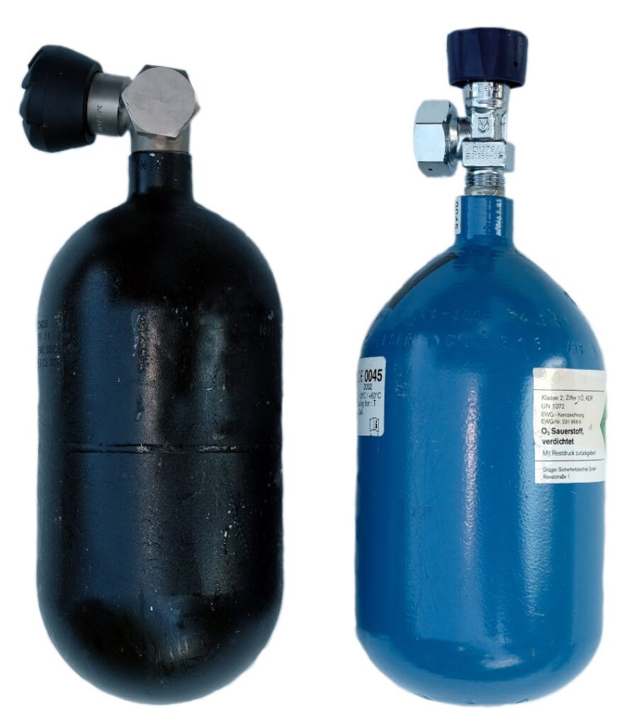
The future belonged to the subsequent models “LAR VI,” “LAR VII,” and other designs, which are not listed here. They are still in use and do not yet deserve the status of a “historic Dräger rebreather device.”
Today’s Dräger oxygen rebreathers for combat swimmers have changed significantly once again. Underwater reconnaissance sensor technology made considerable progress, materials and technology continuously developed, and the scope of combat swimmers’ tasks expanded to greater diving depths. Convertible combination devices from oxygen to NITROX during swimming allow for individually tactical special tasks. One day, it will be enlightening to take a closer look at these current “LAR family members.”
Over the many years of Dräger rebreather device development, special editions and small series were created, which are not described here. They would have exceeded the scope. Additionally, engineers created various experimental setups and test devices to analyze different physical influences, which were exclusively for testing purposes and not intended for regular diving use. This includes an interesting Dräger oxygen rebreather device that was specifically developed as a test device in 1988 for…
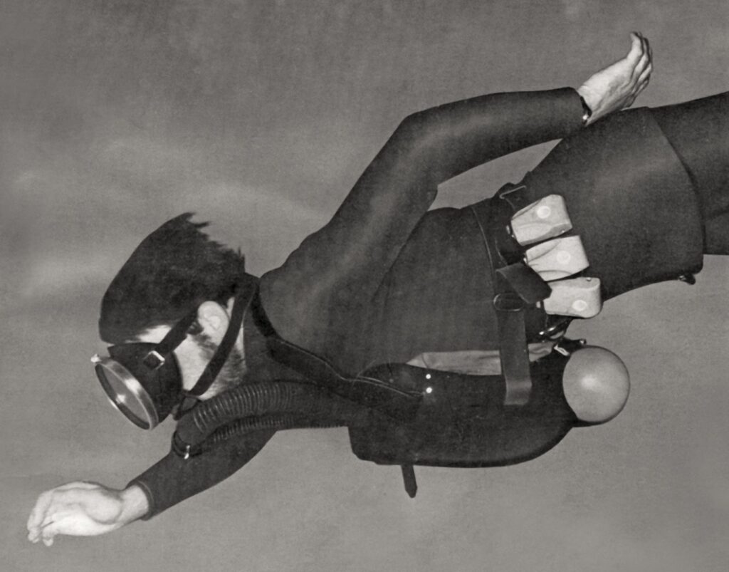
16– LAR V Maintenance Training 1995, Draeger Safety, Inc. 101 Technology Drive Pittsburgh, Archive HK
17– UBA = Underwater breathing apparatus
Page 12 of Part 4 of 4 (page 45)
…designed for cold operations. As the suitability of rebreathers for cold conditions has always been of particular importance, this device is described in more detail below.
The Dräger “KATOX,”
an experimental rebreather device
THE COLD FACTOR
Dräger engineers have long been working on optimizing chemically working CO2 absorbers for rebreathers in laboratory and field experiments, especially with regard to the influence of ambient temperature on CO2 absorber service life depending on a number of device parameters.
The usage time of oxygen rebreathers primarily depends on the service life of the breathing lime (provided that there is a sufficient supply of breathing gas).
Breathing lime consists of a mixture of calcium hydroxide (Ca(OH)2) and additives that are mixed in as stabilizers or pH indicators. The CO2 absorption reaction is typically initiated by the heat (approximately 35°C) and humidity (approximately 95%) of the exhalation air.
All basic requirements for proper absorption, such as the type of lime suited for the application, the appropriate grain size, the best possible flow guidance, and a filling in the lime container without channel formation, cannot, however, prevent a reduced reaction speed with increasing cold.
At temperatures around 4°C, the absorption duration of fresh lime fillings decreases by more than half of the specified service life for almost all types of lime [Image 21].
Lime containers “in the belly” of warm exhalation breathing bags (e.g., Dräger “Lieutenant Lund II”) have a typical advantage here compared to containers that are exposed to the low temperatures of the surrounding water outside the breathing bag (e.g., LAR devices).
To reduce the cooling of these external lime containers, neoprene covers are helpful. However, during operations in icy waters, they often prove insufficient. Additionally, at these temperatures, high condensation water formation contributes to the rapid filling of the water trap in the lime container.
Operations of rebreathers in cold waters repeatedly showed a limitation of dive duration due to reduced CO2 absorber service life. Therefore, a test of lime containers with different wall thicknesses and insulating layers should provide insights into the lime service life in colder environments.
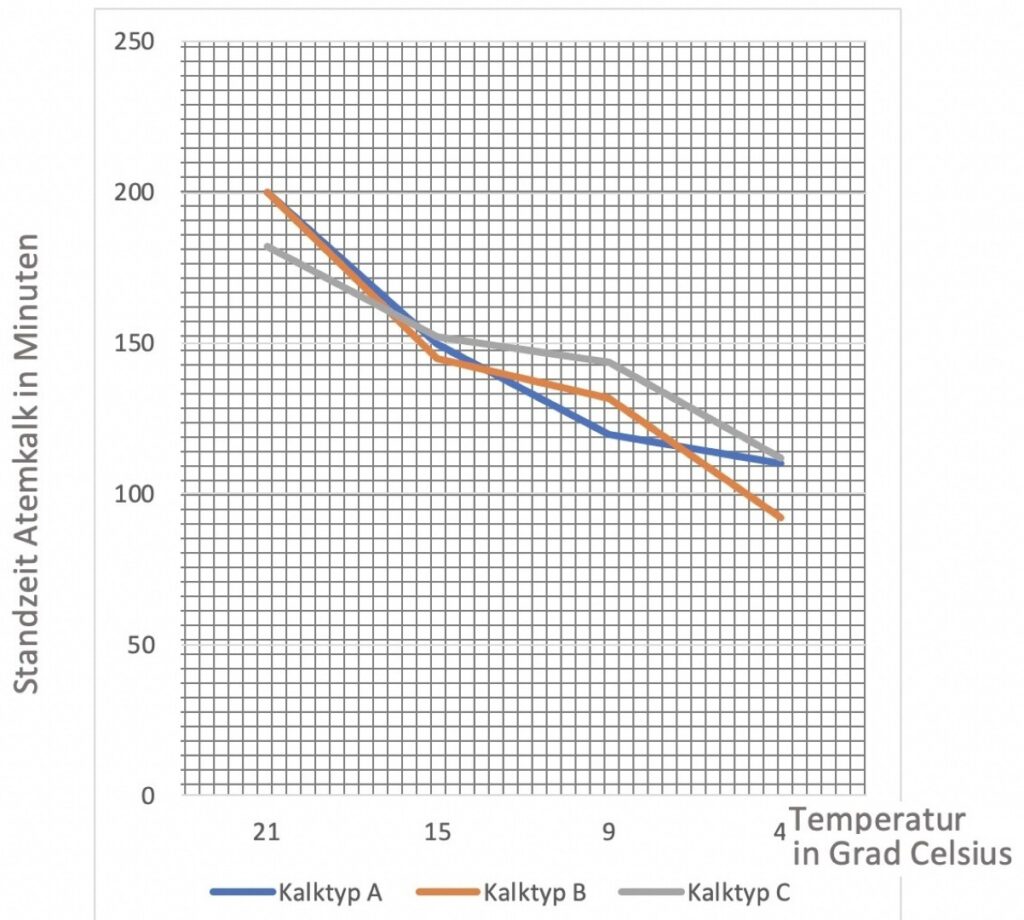
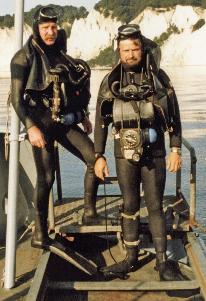
Page 13 of Part 4 of 4 (page 46)
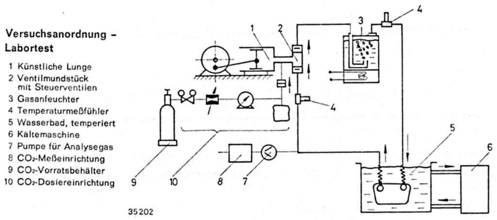
- Artificial lung
- Mouthpiece with directional valves
- Gas humidifier
- Temperature sensor
- Temperature controlled waterbassin
- Refrigerator
- Gas analyser pump
- CO2 measurement
- CO2 storage
- CO2 metering valve
In the mid-1970s, an experimental setup18 [Image 22] was used in lab tests to determine the effectiveness of breathing lime in four containers with different insulation at a simulated exhalation gas temperature of 36°C and saturated humidity…
- with artificial lung, cooling machine,
- controlled addition of CO2,
- various breathing minute volumes and frequencies,
- simulated dive time, and
- different temperatures
The test results showed the different performance of the lime containers at a water temperature of 1.5°C [Image 23]. The lowest insulation effect of the first container made of metal (aluminium) was expected. The second, non-insulated GFK container with a 5 mm thick wall, already showed improved insulation compared to the metal version. The third, GFK container with internal insulating foam, showed even further improved effect, but with the disadvantage of reduced capacity. Ultimately, a 15 mm thick foam on the outside of the fourth GFK lime container provided the desired insulation effect at extremely low temperatures without reducing the filling volume. However, this lime container took up a lot of space due to its larger external dimensions – to the disadvantage of reducing the breathing bag volume.
The results of “field tests” with divers in the open sea during the cold season in northern Norway confirmed that the field tests were comparable with the lab experiments. These experiences were among the foundations for the design of the Dräger “KATOX,” which was manufactured in 1988 to provide insights specifically for cold water use and was made available to swimming divers for testing.
“KATOX,” a hybrid, lung-automated and constantly dosed, was a closed-circuit oxygen rebreather with an O2 constant dosage of 0.7 l/min and additional dosing (bypass) for emergencies, as well as an overpressure valve in the breathing bag [Image 24]. The device also included an automatic lung pre-flushing, which provided an adequate amount of breathing gas upon opening the cylinder valve and inhalation. This eliminated the “manual start” by pressing the bypass valve. The constant flow then took over the further supply of breathing gas.
Two separate medium pressure lines, one for pre-flushing and bypass, the other for the lung regulator, were required for this “hybrid” construction and ensured a reliable supply of breathing gas.
During tactical combat swimmer missions in winter, alternating stays under and above water with the equipment on are not uncommon. Double-digit minus temperatures above water can cause moist zones inside the breathing bag to freeze during use pauses. Technically hardly conceivable, but not excluded, this fate could also befall the lung regulator. These considerations also justified a separate line [Image 25].
The same arguments applied to the shut-off lever of the manometer line at the pressure reducer, an external rubber high-pressure line with a cylinder pressure gauge at the end. An oxygen loss due to the breaking of this line as a result of icing should thus be avoided. The possible freezing of the rotary valve mouthpiece, including the valves and breathing hoses, did not cause concern. They could be thawed out again by warm breathing.
The lime cartridge with a capacity of 2.5 liters of breathing lime contained a second outer cartridge container for cold insulation [Image 26]. It consisted of two halves that enclosed the lime cartridge watertight. Both halves contained condensate drainage valves [Image 27], which especially in very cold water had to be manually…
18– “Studies on CO2 Absorbers for Rebreathers” Dr.-Ing. W. Lubitzsch, Ing. grad. L Schumann
(Dräger issue 309/1977)
Page 14 of Part 4 of 4 (page 47)
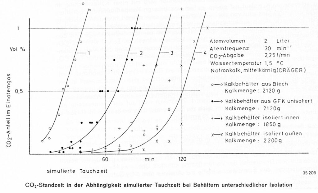
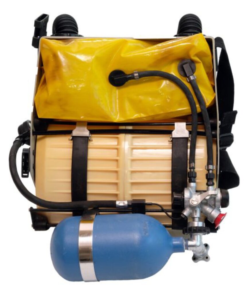
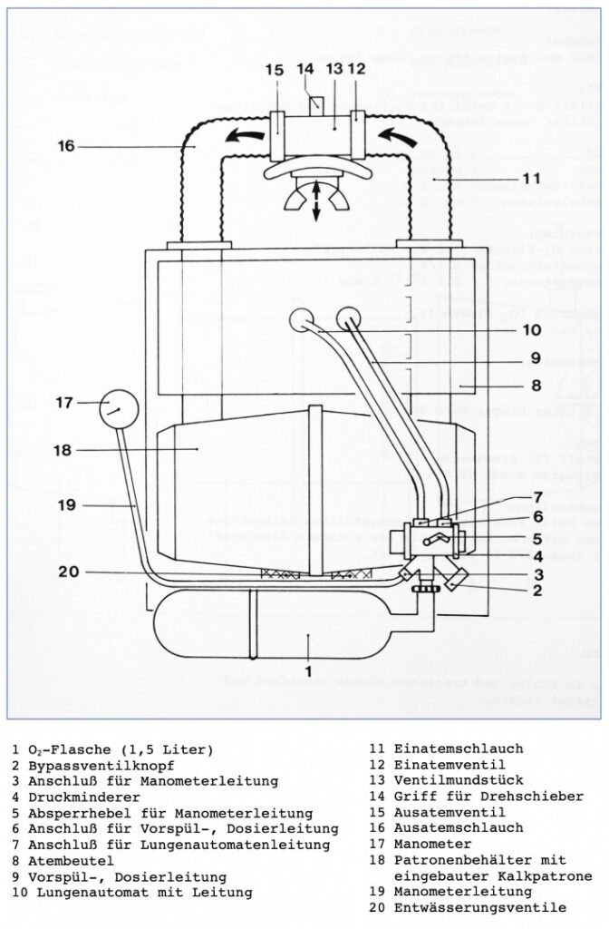
Page 15 of Part 4 of 4 (page 48)
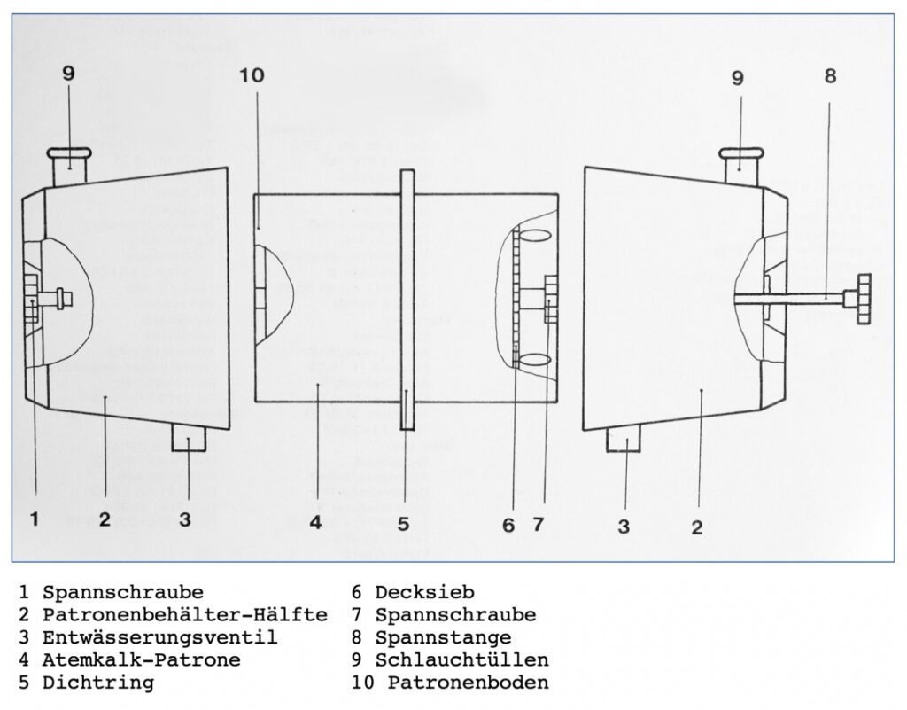
…should be triggered in sequence until gas bubbles escape. For this, the breathing bag had to be completely filled, and the device brought into a vertical swimming position. The device contained a 1.5-liter oxygen bottle (200 bar fill pressure). The breathing bag volume was approximately 5 liters, and the breathing circuit volume was about 8 liters. With dimensions of 420 mm in length, 350 mm in width, and 150 mm in height, the external dimensions were between the “LAR II” and “LAR V.” On land, the device weighed about 10 kg. The “KATOX” was tested by German Navy combat swimmers in the late 1980s during field trials.
The results ultimately showed that effective insulation of the lime container in cold water indeed ensured a longer usage duration. The disadvantage of the larger space required for the lime container ultimately led to the decision to only temporarily use a special neoprene cover for cold water missions. A larger lime container would have inevitably led to a significantly larger device design19.
This concludes the final part of the article on the chronological development of “Dräger diving devices for Combat Swimmers.” Most of the compiled information comes from conversations with former Dräger engineers, military testing and command officers at the time, and former combat swimmers whom I came to appreciate. I am grateful for access to device and document archives, without which many details could hardly have been described. Some information had to be trimmed and simplified, as even after so many years, some aspects still fall under military and civilian confidentiality. Each of the described oxygen rebreathers would certainly be worth its own article, which might be written someday.
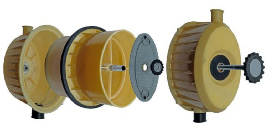
19- Conversations with Dr.-Ing. W. Lubitzsch (successor of Gerhard Haux) and Ing. grad. L Schomann in 2018 and 2019
All illustrations in this article with the captions “© Dräger Archive” are the property of Drägerwerk AG & Co. KGaA, Lübeck. All rights reserved. Captions HK = Helmut Knüfermann

Therebreathersite was founded by Jan Willem Bech in 1999. After a diving career of many years, he decided to start technical diving in 1999. He immediately noticed that at that time there was almost no website that contained the history of closed breathing systems. The start for the website led to a huge collection that offered about 1,300 pages of information until 2019. In 2019, a fresh start was made with the website now freely available online for everyone. Therebreathersite is a source of information for divers, researchers, technicians and students. I hope you enjoy browsing the content!