
Dave offers you a complete manual how to build your own ECCR controller
Diver Dave sent me pictures of the reincarnation of his KISS style rebreather. It came back as a full electronic controlled closed circuit rebreather. Here you find how he managed to do this. Dave thanks for your detailed information!
A big hi to you all out there in dive land from Dave-Rite
Auto add part one
Part one contains all the mechanical parts to the system
AutoCAD drawing may be available when I get the time
Part two contains the electronics
Part three contains the program and programming system
Diving is a dangerous pastime this is for demonstration only
I have been diving on my home built CCR rebreather now for about 4.5 years so I thought that it was about time to build a auto 02 add system.
The following information contained in this document is how I went about building an electronic automatic oxygen monitoring and add system.
The first rule the system has to be tough
Rule two it has to be simple
Rule three inexpensive
Rule fore easy to build with out any special boards.
I think that I managed to achieve all the above with the exception of the hand set this may be a bit of a problem for most people on a budget. You may have to rethink the design of the display housing to suit you resources and needs.
Display housing
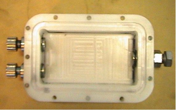
The display housing has been machined from a solid piece of ACETAL the housing can be made from PVC.
I have tried to keep the housing as simple as possible with out compromising function and user ease.
Housing showing the electronics installed end view showing two switches
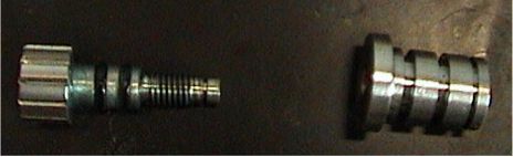
The switches are machined from solid stainless steel
The switches are inserted in to the end of the plastic housing with the orings fitted and are held in place with circlips A rotary action causes pressure on to the switches.
Solenoid Solenoid Fittings
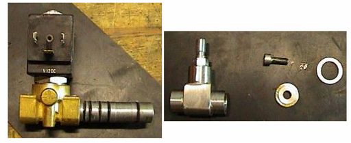
The solenoid is a SMC 12v with 2.5 mill venture the fitting can rotate through 360 Dec and fits a standard inflator house end. Both the solenoid shaft and T fitting are machined from solid stainless but I am sure that standard fitting off the shelf can be found for the job.
The amp housing is made from a piece of stainless steel tube from a steel monger
The cap has been cut out of a piece of 75 mm * 3mm stainless flat bar again from the same monger.
The oring grove has been machined in the cap. Two cable glands made with 3/8 stainless steel UNF bolts. The bolts are drilled through and counter sunk at the end to compress a oring around the cable, the bolts screw in to a female fitting easy to make which are tig welded in to the cap.
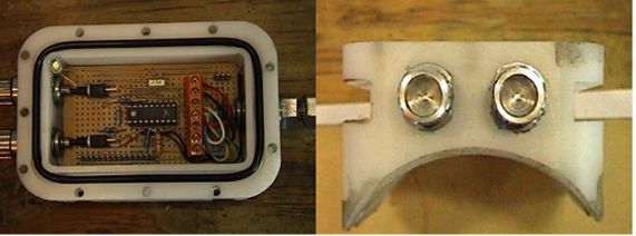
Housing showing electronic board held in place with a piece of nylon that is held to the cap with two screws.
Amp housing open
Cable glands
You can see the little oring
The complete system
It works great Happy building
Welcome to Dave-Rite auto system part two
Part one mechanical part
Part two electronics circuits
Part three programs and programming system
Warning I am not a electro wiz kid, techno geek or computer nerd
The following circuits are the end product of guesswork!
If you use this circuit in a life support system don’t blame me if you have a bad day
So far I have don about 10 hours in the water with this system and found it to be robust, stable, and very user friendly. Most of the diving I do is wreck, between 0 and 120 meters deep and have no problems with this unit so far.
Layout
The system is put together in three sections, this may introduce more leak points having 4 cable gland fittings this is the best way to keep the size of the hand set down and the cost of cables low.
Power block

The system uses two 9v batteries (little square ones) this way I have the higher voltage for the 12v solenoid. F1 Vfet handles the higher currents to drive the solenoid, which draws up to 600 milliamps. The resister R20 270 ohm can be increased to give 6 volts for driving steammachine solenoid valves.
Amp block
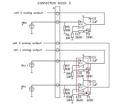
The amp block is fairly straight forward it uses two LM662 op amps there are cheaper amps around but I found that these ones do the job real good.
Cell calibration is done with P1 P2 and P3 multy turn pots.
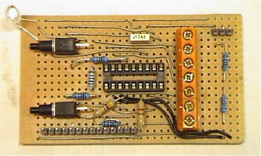
Board 1 picture
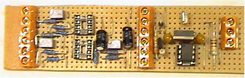
The board is laid out on strip board I do not have the knowledge to make real boards but this works quite well.
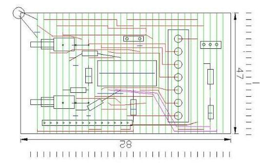
Board 1 layout
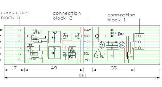
Green lines are board tracks
Read lines are link wire
Blue lines are cuts in the board tracks
PS D2 has been removed
PPS the resistor numbers do not match on the layout to the road maps will update one day
But I am sure you get the idea.
Micro board
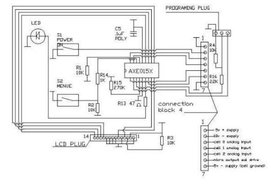
The micro board is again straight forward the micro drives the LCD directly with a 4 way COM line. The programming plug is handy so I don’t have to pull out the micro to reprogram it. C5 must be put in otherwise the micro goes bad.
Picture
Again laid out on strip board
Layout
And the LCD
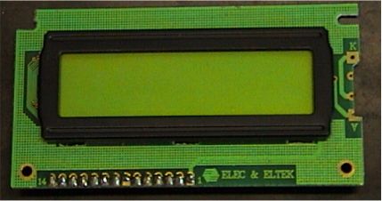
The left hand upper corner has been cut for the LED right hand end cut for the cable gland. I get the LCD from micro zed here in Oz they come as a unit with a firm ware chip and board I don’t use the chip, driving the LCD directly from the micro is far more reliable then serial interfacing. These LCD are easy to read under water and about the best around for the price.
Have a nice day
Welcome to Dave-Rite auto system part three
Part one mechanical part
Part two electronics circuits
Part three programs and programming system
Danger I am no keyboard monkey, micro-pain, or cyber-warrior
The following program is the work of king Neptune.
If you use this circuit in a life support system don’t blame me if you have a bad day.
The hart of the system is the Picaxe micro controller these systems are incredibly easy to learn and use.
You can down load the programming program from www.picaxe.co.uk but please read the license agreement for personal use only.
After you have loaded the programmer in to your computer, build your controller plug it in to your computer; flash up the Pic and away you go it’s as simple as that.
Test board
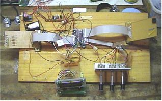
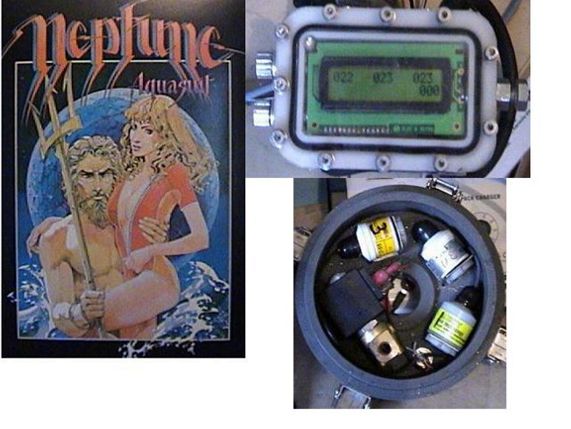
Above is a picture of the test board that I developed the soft ware on. I call it the Dave-Rite dive simulator, all the following pictures are taken from the simulator not from the unit it self. I made it up from a pic 28X experimenters kit, three pots which I used to simulate the o2 cells inputs, and some LED, s to represent solenoid outputs etc,
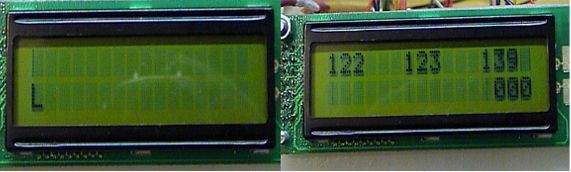
Above right is the LCD screen when you first turn the unit on it shows the three cell readings along the top line and the loop count bottom right.
The way the program works, the core of the program reads the cell voltages and writs the cell values to the screen by a subroutine this I call the main loop (RECELL) every time this loop happens it counts. After a preset count the count resets to 0.
The count can be used for a visual check that the micro is not hung up.
Above Right, the letter bottom left of the screen shows the operating mod L for low set point H for high set point M for manual the solenoid dos not inject when in manual.
The mod can be changed any time on the run by using the menu switch.
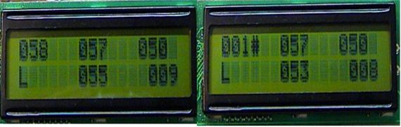
Above left operating in low set point the second number on the second line is the average of the three cells.
Above right operating in low set point cell 0 has an astras beside it indicating that it has been voted out of the average because the cell has gone low. The unit needs two cells reading correctly before it will take an average the average is what it uses to estimate the PP02.
If a cell goes high compared with the other two cells the unit goes in to alarm.
It has three other alarms low PPO2 high PPO2 and cells out of range.
The three cell readings are updated twice a second, when the loop count reached reset the micro checks the cells for out of range, takes average, then injects or no injects depending on PP02 level.
The loop time changes with error from set point.
The injection time changes with error form set point.
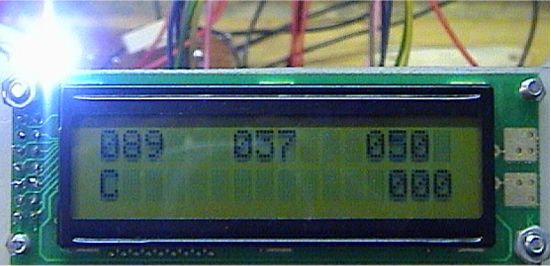
On the next page is a picture of the unit in alarm mode cell 0 has gone high compared with the other two cells the high intensity LED flashes and a C is written to the bottom left corner indicating a cell alarm. In cell alarm and high PP02 alarm the solenoid stops operating until the alarm state has been reset and the problem fixed or it is operated in manual mode. And if you are having a real bad day you go semi closed or bailout.
I dive this unit Neely every weekend on wrecks to 80 meters and it has never locked up or stuffed up other then cell problems, which happen whatever system, you use.
If you do build something like this make sure you test it real good there is no second chances in home building game.
And have a nice day.

Therebreathersite was founded by Jan Willem Bech in 1999. After a diving career of many years, he decided to start technical diving in 1999. He immediately noticed that at that time there was almost no website that contained the history of closed breathing systems. The start for the website led to a huge collection that offered about 1,300 pages of information until 2019. In 2019, a fresh start was made with the website now freely available online for everyone. Therebreathersite is a source of information for divers, researchers, technicians and students. I hope you enjoy browsing the content!
WARNING: This page and this information is only for study purposes. If you use this information to build a ECCR controller know what you are doing. If you use this system in actual diving the you might get killed or injured. This information is only for building a controller to understand the working principle. If you want to use it for actual diving you will need a certified and tested system with CE marking in Europe!