
Explanation of the energy balance by physicist Halbert Fischel
CLOSED-CIRCUIT CRYOGENIC SCUBA
Halbert Fischel
Sub-Marine Systems Corporation
A Sterling Electronics Company
Chatsworth, California 91311
1970
ABSTRACT
Rebreathed gas is partially routed through the cryogenic processor, described in an earlier paper I, after being scrubbed chemically for removal of CO2. This results in a weight and volume reduction by a factor of two or more. The breathing loop and cryogenic system design are modified to operate in conjunction with a Venturi-type proportional flow separator. Beginning with the theory of the semi-closed circuit method and observing that, in effect, cryogenic processing is used here only to fully close the breathing loop, the pertinent theoretical considerations are explained in detail. A thermal and moisture regenerative technique substantially mitigates respiratory heat and water loss from the diver by restoring better than 90% of both to the respiratory exchange and, at the same time, removing a great deal of the water burden from the desiccating unit used to dry the gas before it enters the cryogenic portion of the system. The theory governing heat and mass transfer relationships which lead to a practical and effective design of a unit for insertion in conventional mouthpieces or face masks is presented. The latter device is referred to as an oral regenerator (OR).
INTRODUCTION AND RECAP OF THE BASIC PROCESS
The basis for the work reported here is an earlier system employing cryogenic means for controlling p02 and scrubbing CO2 in fully-closed circuit SCUBA. There, the entire breathing medium is recirculated through a cryogenic processing system with each respiration cycle. Cryogenic processing is defined for purposes of this paper to consist of counter-flowing gases brought together in intimate thermal contact without mixing in a heat exchanger which effects cooling of the exhaled gas by concomitant warming of the gas to be inhaled. Cooling brings about precipitation of solid CO2 which is held within the system for subsequent warming and purging after use. The cold end point is controlled by the regulated temperature of the liquid oxygen (LOX) with which the circulating gas is thermally equilibrated. Facilitated by appropriate wick design which presents an expanded liquid gas interface, a condition of saturation is established whereby the p02 is fixed, i.e. dependent upon the LOX temperature but otherwise invariant with-changes in respiratory rate or depth pressure.
A system which embodies these principles is illustrated in Figure 1, showing the respiratory flow loop and process steps. Beginning with the exhaled breath, the gas leaves the mouthpiece or mask and passes from a breathing bag through a desiccant filter. Pre-scrubbing, to remove the bulk of the CO2, may optionally proceed the desiccant, but is not absolutely required. Its use reduces the load on the stored refrigeration used to maintain cryogenic temperatures and contributes to extended duration, thereby. At the point of entry to the desiccant, a tangential line is connected to permit the injection of helium Into the system to balance ambient depth pressure. The diver controls the inlet valve at will and permits that amount to enter from the high pressure helium storage bottle required to adjust his buoyancy and provide for comfortable breathing.
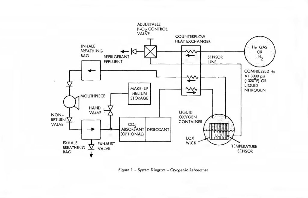
After the gas has been desiccated to a dew point of approximately -60°F it enters the counterflow heat exchanger which cools it to just above the temperature of the LOX. Ultimate thermal equilibrium with the latter results in saturation of the gas with oxygen vapor. Evaporation of oxygen provides the cooling for removal of the residual sensible heat remaining in the gas which had entered the LOX container after leaving the heat exchanger. This brings the LOX, oxygen vapor and breathing gas to a uniform temperature; a process which is accelerated by the expanded surface of the cryogenic wick and heat pipe disposed within the LOX container.
The temperature of the breathing gas at this point is approximately -320°F or higher, depending upon the partial pressure of oxygen desired. At these temperatures, the partial pressure of CO2 cannot exceed 25 PPM, surface equivalent. Over 99″/o of the cryogenically-scrubbed CO2 was deposited in the heat exchanger in a manner described in the earlier paper. Figure 1 also shows an auxiliary cryogenic refrigerant container which is used in an open loop fashion to provide cooling to the LOX on a regulated basis in order to maintain the latter’s temperature at the preset value. A nitrogen vapor pressure thermometer disposed in the LOX container provides the signal needed to regulate refrigeration output From the auxiliary cryogenic vessel and cooling fluid is released to the heat exchanger on demand from the temperature controller. The additional cooling is required to offset heat loads imposed by the circulating gases and conduction through cryostat insulation and plumbing. If all the carbon dioxide is removed by Freezing, then the latter’s heat of crystallization becomes the major contributor to the overall heat load. A trade-off of refrigeration volume versus chemical scrubber volume favours the latter in the case of open loop refrigeration. Thus, removal of the bulk of the CO2 by chemical means, Followed by virtually total removal of the residual CO2 by cryogenic Freeze-out leads to a system which is optimized for size and weight, while preserving the Fail-safe advantages of cryogenic processing of the entire respiratory gas budget as reported earlier.
The principal advantage of the earlier configuration, which fully recirculates the breathing medium through the cryogenic processor, is availability of extremely thorough and fail-5afe cryogenic CO2 scrubbing to the entire rebreathing gas budget. This permitted the exclusion of chemical CO2 scrubbers from the system if, For any reason, these should prove ineffective or otherwise unsuitable under the intended conditions of operation. In some instances undetected defects in, or absence of, chemical CO2 scrubber has led to fatal accidents2. Extremely cold water can potentially, and rather
drastically, reduce the effectiveness of most chemical scrubbers. Although cannister insulation alleviates this difficulty somewhat, the increased heat capacity of gas at greater depths can completely outweigh heat loss by conduction, making it very difficult, indeed, to sustain necessary absorbent bed operating temperatures.
Nevertheless, the combined use of chemical scrubbers and cryogenic processing can result in major weight and volume saving never before possible in bock-pack design and the choice becomes a matter of trade-off. Under certain conditions of use where good controls are in effect and the water temperature is not too cold, the reliability of chemical CO2 scrubbers can be very goad and their use, for which there is really no alternative at this time other than cryogenic SCUBA, is indicated. In fact, every fully or semi-closed circuit breathing device, with the single exception of the cryogenic rig, uses some form of chemical CO2 scrubber. The previously reported cryogenic unit, which does not, has approximately the same size and weight as the best of the electronically regulated closed circuit rigs, i.e., 70 lbs. neutral for 5 hours at 1,000 feet. The alternative configuration described in the following paragraphs uses a combination of cryogenic processing and conventional rebreather design, comprising a system which can be packaged in a compact neutrally buoyant envelope weighing only 30 lbs, while still capable of the same performance and duration of 5 hours at 1,000 feet.
RATE BALANCED REBREATHERS
A considerable body of work has been carried out which endeavours to balance the rate at which oxygen is consumed by the diver, with a corresponding rate of oxygen injection so that its concentration neither accumulates to excess nor becomes depleted, Solutions to the problem of p02 invariance with changes in both depth pressure and respiratory rate have evaded all but those systems which employ some form of closed loop control with a p02 sensing element providing a feed-back signal For servo-controlled operation of the 02 supply. Open loop control implies the absence of corrective feed-back. The most noteworthy of these is the semi-closed circuit rig, employing a fixed mass injection rate of oxygen-bearing gas and re-circulation of the breathing medium through chemical CO2 scrubbers. As excess gas accumulates, it is expelled to the ocean through a non return valve, usually located in the exhale breathing bag, This concept is the basis for virtually every semi-closed rebreather design in existence, regardless of the engineering details of valve and orifice design.
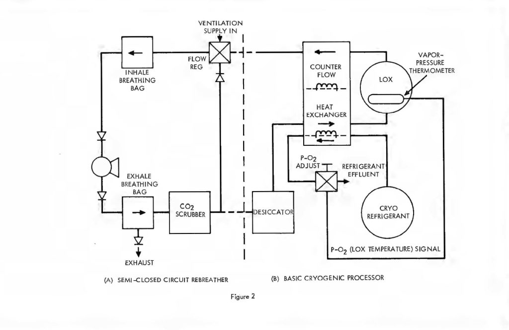
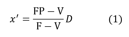
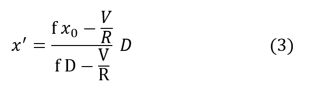
It is instructive to begin the analysis of the rate balanced cryogenic system with an analogous treatment of semi-closed devices. Figure 2 (a) is a schematic of the basic semi-closed system. A supply, external to the principal breathing loop, delivers oxygen bearing gas either from a back mounted high pressure storage bottle or through an umbilical line. This gas enters the breathing loop either before or after the CO2 scrubber. For convenience, the diagram shows the gas entering after the scrubber relative to the direction of gas flow, which is counter clockwise in the drawing, Excess gas is expelled from the exhale bag and flow is directed by means of non-return valves. If F is the fixed mass inlet rate in standard atmospheres and P is the percentage of oxygen by volume then FP is the rate at which oxygen enters the breathing loop in surface equivalent or standard atmospheres. If V is the rate of oxygen consumption by the diver and D is his depth pressure in atmospheres, then one balances the mass flow of oxygen to and from the breathing loop as follows:
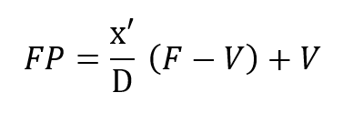
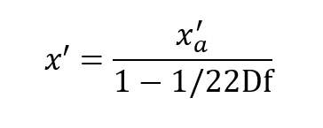
where x’ is the partial pressure of oxygen in the exhaled breath so that:
This mass balance is based upon the fact that if a mass F is entering the loop and V is leaving it through metabolic consumption of oxygen then the difference F – V must also leave the loop through the exhale bag if the system is to maintain a constant gas volume.The mass of CO2 input which otherwise offsets the oxygen withdrawal at the diver is neglected since it is absorbed elsewhere in the loop. Therefore, the mass of oxygen leaving through the exhale bag is given by its percentage, or x’/D times the total massflow, F – V, exiting.Similar application of what are, in effect, Kirchhoff’s laws applied to mass flow to the node at the mouthpiece yields:
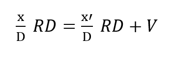
where x is the partial pressure of oxygen in the inhale gas and R is the respiratory minute volume or volumetric breathing flow. RD gives the respiratory exchange in standard atmospheres, Thus:
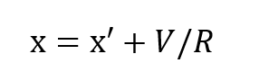
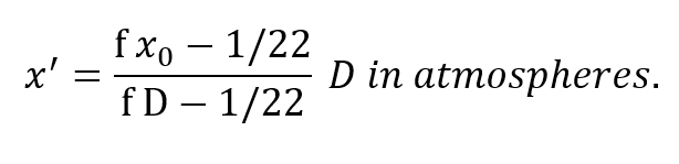
It has been shown, rather conclusively3, that the ratio of standard oxygen consumption to the respiratory minute volume is a constant which varies only negligibly over a very wide range of metabolic rates and ambient pressures. The value of this constant is very close to 1/22, that is (to within approximately ±10%):
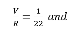
In other words, the difference in p02 between the inhale and exhale breath is 1/22of an atmosphere or 0.67 psia regardless of depth, respiratory rate or oxygen concentration in the gas. This is entirely consistent with the process whereby oxygen bearing gas perfuses through the alveolar spaces and then diffuses through cell tissue to be exchanged for CO2 in the hemoglobin. Once a partial pressure differential of 1/22 atmosphere is established, the lungs must be ventilated before further oxygen transfer can take place. In effect, when the body requires more oxygen it breathes proportionately faster taking the same amount from each volume exchanged. In fact, the process of respiration is driven by CO2 build-up which is directly tied to metabolic rate. Thus,the assumption represented by equation (2) is well founded on the basis of experimental evidence.
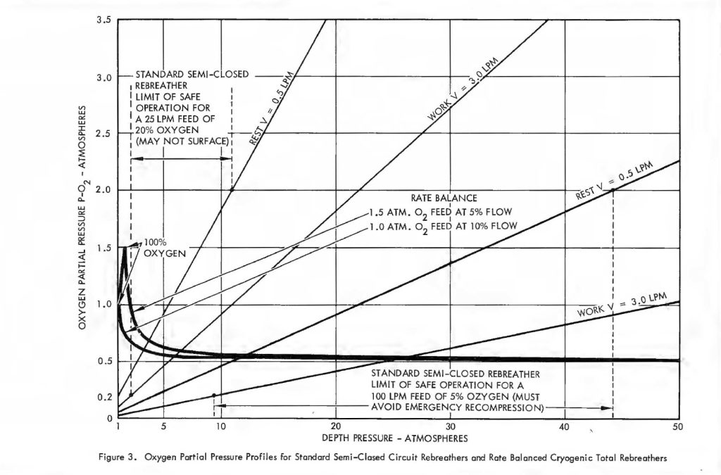
Remembering, then, that there is only a small constant difference between inhale and exhale p02 it is convenient to examine the behaviour of the parameter x’ under variable conditions of respiratory rate and pressure. Figure 3 shows some typical curves of p02 versus depth for several 02 consumption rates. Of course, p02 Is proportional to depth, just as with ordinary open circuit SCUBA gear so the mix has to be carefully selected for the depth at which it will be used. The problem is compounded by the variation of p02 in the wrong direction with changes in diver exertion. That is, as V increases, x decreases making it even more difficult for an exhausted diver to get oxygen. Some examples are very revealing. Suppose a diver is operating at 30 atmospheres depth pressure. If his supply is self-contained, the breathing loop ventilation rate is usually restricted to about 25 liters/minute. At rest, the diver may use only 0.5 liters/minute of oxygen and one may not want his p02 to exceed 1.5 atmospheres because of oxygen toxicity limits. Thus, according to equation (1) the percentage of oxygen in the feed gas may not exceed 7%. On the other hand, his exertion level could easily increase to 3 or even 4 liters/minute of 02 consumption, but under the stated conditions his p02 level went to zero at a consumption rate of 1 .7 liters/minute, which is merely a sustained moderate work level! When the ventilation gas is supplied from an umbilical, the system is usually more generous and as much as 100 liters/minute is sometimes delivered. Using the same criterion of a maximum p02 of 1.5 atm., the umbilical gas cannot exceed 5.5% 02. However, the p02 does not fall to dangerously low levels until the diver is consuming about 5 liters/minute of oxygen. Some will do even this under extreme exertion. A system which drops the p02 from 1.5 atm. at rest to 0.15 atm. under extreme exertion using an umbilical ventilation delivery of 4 cfm. without yet having accounted for possible depth changes should be regarded with great caution.
In the opinion of the author, the greatest potential hazard with the semi-closed system is even more subtle. It derives from the fact that most divers find it difficult to get enough gas when working hard at great depth. They invariably feel that the system does not flow fast enough or is otherwise restrictive to their breathing which elevates them to higher levels of exertion and compounds the problem. They usually resort to the inlet bypass valve and run full open circuit, breathing raw gas from the umbilical.If the latter is too rich in oxygen, as adjusted for semi-closed operation according to equation (1) they are subjecting themselves to serious oxygen toxicity. An accident such as this is easily attributed to other causes and, as a result, has probably never been properly diagnosed.
The rate balanced cryogenic rebreather avoids all of the difficulties described above byclosing the breathing loop as shown in Figure 2. The (a) portion of Figure 2 is thesemi-closed system just discussed. The (b) portion is a cryogenic processor. When thetwo are joined, the exhaust gas which normally exits through the exhale breathing bagin the semi-closed configuration, is directed, instead, through the cryogenic processor.After running through the cryogenic loop it reenters the principal breathing loop at thepaint where fresh ventilating gas would normally enter in the semi-closed system. Theexternal supply is no longer used except for make-up gas to equalize depth pressure orcontrol buoyancy. Thus, no gas escapes from the system (except, of course, duringascent) in the course of the rebreathing cycle. The auxiliary loop, through the cryogenicprocessor, saves the gas which is otherwise lost but, more importantly, resuppliesit to the breathing loop on an entirely different basis. In this case, the gas is suppliedat a fixed partial pressure of oxygen rather than a fixed percentage. What is more, thequantity of gas making the cryogenic circuit is proportional to or, in fact, a fraction ofthe total recirculated flow, rather than a fixed mass inlet rate as in the case of thesemi-closed circuit system. This is accomplished by means of a Venturi-type or aspiratingflow divider in place of the fixed moss inlet regulator. Inspiration draws the mainbody of gas through the shunt line and a small but constant fraction through the cryogenicloop. The analysis of this circuit is somewhat more complex, but is easily treated by theapplication of Kirchhoff’s laws. Suppose a respiration rate of R draws the fractionalflow fR from the cryogenic processor and (1-f) R across the shunt line. Then balancingmasses flowing into and out of the main breathing loop yields:
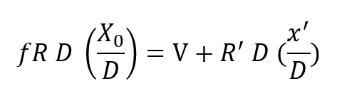
where Xo is the fixed oxygen partial pressure supplied by the cryogenic processor and R’is the flow drawn into the processor from the breathing loop. Applying total mass balance at the LOX vessel one has masses R’ D and V flowing into the loop at that point and mass f RD flowing away from this node. Thus:
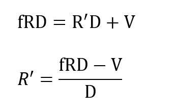
and substituting R’ in the previous expression gives:
Using equation (2):
The most important result is already apparent, namely, the PO2 of the respired gas is entirely independent of breathing rate. Further insight into the behavior of this equation is seen by rewriting it:
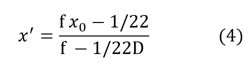
Clearly x’ is not proportional to depth but is rapidly asymptotic to a fixed value withincreasing depth pressure, approaching the value:
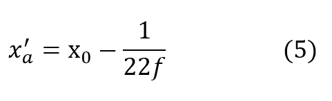
very closely by the time D exceeds 2 or 3 atmospheres for most practical values of f.It is seen that the cryogenic modification just described yields a fully closed circuit rebreathing system, which maintains respired P-02 substantially invariant over all useful ranges of depth and respiratory rate.
Using equation (5) for the asymptotic value of x’ denoted by x’a equation (4) may be written:
The maximum possible value of x’ is when x’ = D which represents 100% oxygen.
This occurs when:
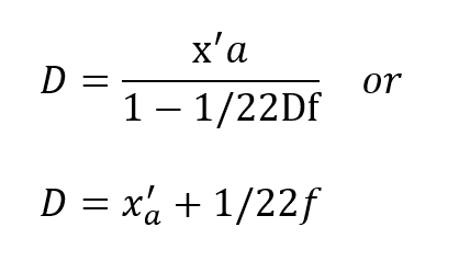
From equation (5) this condition represents:
Thus, the obvious may be concluded, namely, that the respired PO2 cannot exceed that provided by the cryogenic supply which is fixed at x0. More important, however,is the fact that this does not occur until the depth pressure matches the O2 partial pressure, a situation obtaining only in shallow water. Actually, the tendency for the PO2 to rise sharply to the 100% 02 limit in shallow water is well suited to the latest techniques of decompression which elevate the 02 level as a means of purging the tissues at the end of the decompression routine.Some examples are given in Table I for a x0 of 1.0 and 1.5, respectively. The variation of f far different values of x’a show that f is greater, but less critical for lower values of x0.
TABLE I
RATE BALANCE PARAMETERS
| X0 = 1.5 | x’a= 0.5 | f = 5% |
| – | 0.4 | 4.6% |
| – | 0.3 | 4.2% |
| – | 0.2 | 3.9% |
| X0 = 1.0 | 0.5 | f = 1.0% |
| – | 0.4 | 8.4% |
| – | 0.3 | 7.2% |
| – | 0.2 | 6.3% |
For x0 of 1.0 atm. a 40% error in f changes the pO2 from 0.5 to 0.2 atm. within safe limits. Thus, the system is not difficult to adjust and is basically stable. Figure 3 shows the variation of pO2 with depth in accordance with equation (4) for the two values of x0 used in Table I. It is easy to see why these pO2 profiles are of considerable advantage in any diving and decompression routine, particularly when compared to the pO2 profiles for the conventional semi-closed circuit configuration. The transient effects of rapid ascent were not considered in the foregoing analysis. At some point in an ascent made gas must be lost from the system through the exhale bag exhaust valve. This carries oxygen out of the system and tends to dilute the latter. The effect can be completely suppressed, however, by allowing some of the gas to vent through a line passing through the LOX container which will evaporate a sufficient quantity to completely offset the amount that is dumped overboard.
The overriding consideration, in going to the rate balanced configuration as opposed to a totally cryogenic processing unit, was size and weight. It is now clear why the reduction is possible. Because the refrigeration load is proportional to the square of the circulating mass flow, reducing that flow by a factor of 10 or 20 for values off = 10% and 5%, respectively, cuts the refrigeration demand by a factor of 1/100th to 1/400th of what it would otherwise be. At these levels the evaporation of oxygen is enough, under most operating conditions, to offset the circulating and conductive heat loads and provision for additional cooling is very easy to provide in a small volume.
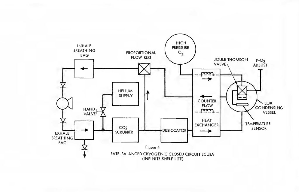
Indeed, the rate balance configuration makes it possible to use a Joule-Thomson expansion valve in a LOX condensing vessel to provide all the refrigeration necessary without staring any cryogenic fluids whatever. Figure 4 shows the rate balanced system with a high pressure oxygen supply vessel. Oxygen, under pressure (initially 3,000 psi or greater), is admitted through isolated portions of the counter-flow heat exchanger and expanded across a Joule-Thomson orifice in the LOX vessel. Expansion cools the O2 to LOX temperatures. The actual temperature is still sensed by the vapor pressure thermometer which ultimately regulates the release of oxygen from the storage vessel, thereby controlling the LOX temperature. The process is identical to the Joule-Thomson open cycle coolers used by the Air Force in thousands of infrared detection units. Essentially,the high pressure inlet gas is first cooled down as it passes through the heat exchanger. Expansion cools it further and it returns to assist in cooling the heat exchanger on a counter-flow basis. Starting with ambient temperatures throughout, it is possible to get to LOX temperatures in a matter of seconds from a bottle charged to 3,000 psi. There is no need to store cryogenic liquid in order to have a cryogenic system with this configuration and virtually infinite charge shelf life is possible.
In any case, the system is considerably smaller and lighter than the straight cryogenic processor because the heat exchanger, cryogenic refrigerant supply and desiccant have all been greatly reduced in size. The O2 supply itself is still about the same and the CO2 absorbent becomes the dominant component in both weight and volume.
ORAL GENERATOR
Another method for reducing the bulk of a cryogenic system while adding significantly to the comfort and well-being of the diver is by means of an oral regenerator described in a previous paper by the author 1. One of the basic deficiencies of all portable systems designed for the support of the human breathing function is in the lack of control of the gas supply’s temperature and humidity for breathing. These systems all supply breathing gas obtained from a storage of either very high-pressure gas or liquefied gases at cryogenic temperatures. When these gases are converted to ambient conditions(either expanded in the case of high-pressure storage or warmed to ambient temperature in the case of a liquefied cryogenic gas), there is a near-zero amount of water vapor in’the gas, generally much less than 1% relative humidity. When the diver breathes a very dry gas for several hours, the drying-out of the mouth and throat passages produces extreme discomfort. Also, the supplying of water vapor to the breathing gas that is exhaled draws a rather large amount of heat from the body through evaporation in the lungs. Since the ambient temperature encountered in the environments that typically employ these portable breathing systems (divers working at great depths, pilots at very high altitudes and firefighters engaged in their basic task) are not really suitable for the human body temperatures, the heating or cooling of the breathing gas by the human body can place severe loads on the human’s body temperature. These can severely restrict the efficiency of the human over the course of several hours working. Typically, with a diver working at a depth of 300′ below the surface, in a normally-encountered 50°F environment, the heat that he needs to supply to his breathing gas to bring it up to 98.6°F temperature and 100% relative humidity at the point of exhale, can represent 20″/o to 30% of the total heat loss of his body. Moreover, this heat loss is occurring at a point very close to his internal organs and probably has mare effect on the overall efficiency of human performance than would an equivalent heat loss at the surface of the limbs. It will be shown in the subsequent paragraphs that a rather simple, though nonetheless sophisticated, regenerator to conserve both heat and humidity of the exhaled breath can be designed to resupply this heat and humidity to the next inhaled breath. This regenerator can be used with these various portable breathing systems and can be so designed small enough and efficient enough that all the other functions of the breathing system are either unaltered or affected to a negligible degree.
The thermal regenerator is an amazingly simple yet efficient device. It was first employed by Robert Stirling in his prime mover used in the 19th Century, and has subsequently seen use in various modifications of the Stirling engine and refrigerator andalso in a more efficient turbine prime mover. Additionally, it has seen much service in process plants; particularly in fractionation of cryogenic liquids. The device is schematically shown in Figure 5.
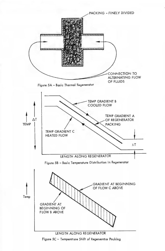
Figure 5-A shows that the basic regenerator is simply a volume, this volume so placed such that an alternating flow of gas (e.g., the volume of air that passes into and out of the human lungs) passes alternately in each direction through the regenerator. The material that Fills the regenerator volume is very finely divided. A typical material that might be used is compressed copper wool. As the gas passes through this very finely divided mass it readily gives up heat or takes on heat, depending on whether the gas is cooler or hotter than the mass at a particular point. This effect is schematically diagrammed in Figure 5-B. This figure shows the temperature profiles along the length of the regenerator. The temperature profile of the regenerator packing is labelled gradient A. The temperature profiles Band C are those of the gas alternately traversing in the cooling and heating flow directions, respectively. For example, the flow direction in the case of gradient B is that in which the gas undergoes a coaling or lowering of temperature as it passes through the bulk of the regenerator material. The basic profile gradient “A” is somewhat idealized,in that as the gas passes through in each direction or that period of time which the unidirectional flow is maintained, the regenerator packing undergoes a slight heating or coaling of the bulk material and therefore the temperature gradient is not a fixed relationship with time but moves slightly during the time period of the unidirectional flow only to reverse and cycle back to the beginning gradient during the period of reverse flow. This effect is schematically diagrammed in Figure 5-C which shows how a highly efficient regenerator alters its profile from one extreme ta another during cold passage time. The mathematics quantizing the effects that occur within a regenerator during the oscillating flow cycle are quite complicated and difficult to manipulate. Fortunately, an approximate relationship has been worked out by Cowans 4 for fallowing the original work of Hausen 5 for very efficient regenerators (efficiency greater than 90%) in which the temperature shift of regenerator packing integrated over the whale length of packing is less than 1/3 of the temperature change from one end of the packing to the other. These relationships are summarized below. A basic reference far the meaning of the terms used is McAdams Heat Transmissian6.
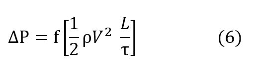
The relation for pressure drop undergone by a gas as it passes through a regenerator packing is conventionally described by the Fanning relationship, equation (6) in which ∆P is the pressure drop undergone by the gas, f is the Fanning friction factor, ρ is the average density of the gas, V is the velocity of the gas going through the regenerator packing, L is the length of the packing and τ is the radius of the pocking defined by the ratio of volume per unit heat transfer surface.
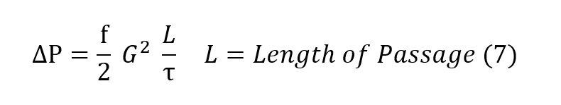
In more useful terms, the Fanning equation is described as equation (7), where G is the
mass flow per unit cross sectional area of the regenerator.
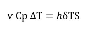
The heat transfer undergone by the gas as it traverses the regenerator is described in conventional terms by the following equation in which h is the conventional Newtonian heat transfer co-efficient. S is the heat transfer area, ѵ, is the total amount of gas passing through the regenerator, Cp is the specific heat of the gas at constant pressure, δT is the temperature difference existing between the gas and the regenerator packing at any paint within the regenerator (Figure 5-B) and , ∆T is the temperature change that the gas undergoes between the entrance to the regenerator and the exit.
Again, in more usable terms, employing G, the basic heat transfer equation is as follows:

Dividing the Fanning equation by the basic heat transfer equation, and expressing the ratio h over CpG in terms of the more conventional Colburn modulus, h over CpG times the2/3 power of the Prandtl number (Cpμ/k), the basic regenerator design equation is given below, wherein it may be seen that the pressure drop through the regenerator divided bythe total heat transfer potential of the regenerator is proportional to the inverse of the cross sectional area squared for a given amount of mass flaw.
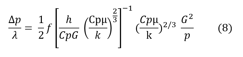
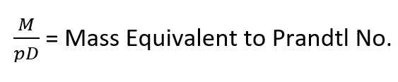
In more descriptive terms, the design equation (8) shows that the regenerator may be made as short as desired with no first order effect on efficiency and the pressure drop may be made as law as desired as long as the crass sectional area can grow. In real terms, to give an operational example, far a respiratory pressure drop across the regenerator of less than 0.1″ of water, designed for use at 600′ depth an helium/oxygen and taking a respiratory minute volume of one cubic foot per minute, the design equation shows that this would require a breathing regenerator approximately 2-1/2″ square. Of course, this cross sectional area can be arranged in any convenient manner. Typically, this 2-1/2″ square regenerator could be wrapped in a tube to easily fit within a conventional mouthpiece and the resulting tube would be an approximate 8/10″ in diameter by 2 inches long. The relationships given above show haw a regenerator can be used ta transfer heat quite efficiently and in the example given, if the human were working in an ambient of 50°F instead of inhaling gas at that temperature, he would be inhaling gas approximately 94°F,if his exhale gas were at the expected 98.6°F. Moreover, the regenerator works equally as well to conserve humidity exactly as it conserves heat. The relationship of the heat transfer equation for mass transfer is exactly the same with the appropriate terms exchanged as given in the equivalent relationship below.
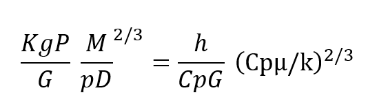
Kg is Mass transfer co-efficient, P= Vapor Pressure of Humidity
These parameters follow the explanation given in McAdams6. Without getting into too deep a detailed explanation, it is probably sufficient to say that the moisture in the gas which is originally at 100% relative humidity and 98 .6°F is deposited on the surface of the packing in a manner exactly analogous to the way heat is stored within the body of the pocking and this moisture is extracted from the body of the gas. The transport mechanisms that are related on a direct basis to the thermal conductivity and molecular diffusivity enters into the transfer of heat within the body of the gas to the surface of the pocking. In general,if a regenerator is 90% efficient in terms of heat transfer, it will be approximately 90%efficient in terms of mass transfer. That is, if the diver again is exhaling gas at 98 .6°F and 100% relative humidity, into an environment that is at 50°F. The gas will eminate from the cold end of the regenerator and pass approximately 55°F and 100% relative humidity at that temperature. Therefore, the regenerator is about 90% efficient in terms of the heat retained; that is, instead of the gas emerging into the surrounding environment,50°F hotter than the environment, it is only 5° hotter or 10% of what would exist if the regenerator were not there. Likewise, about 90% of the humidity that was in the original breath is also stored within the regenerator, to be returned to the diver on the next inhale breath.
Moreover, it is possible to conserve mass, that is, humidity in our case, on the surface of a special regenerator packing even in the total absence of a temperature difference from one end of the regenerator lo the other. The way this is implemented is to make the regenerator packing of an absorbing material. A good example and probably the most likely candidate for this material would be activated charcoal. Here, the conceptual relationships are not quite as simple as in the elementary thermal regenerator but the same basic parameters govern. In place of the specific heat of the regenerator being capable of storing a certain amount of heat while being moved in temperature only a few degrees, the absorbing material has a unit volume capacity of a certain amount of mass that it can absorb if the external vapor pressure of water is larger than the vapor pressure of water internal to the body of the absorbing material. Or, in other words, the absorbing material will absorb an equilibrium amount of water vapor at a given vapor pressure of water over the absorbing material and the amount of material absorbed is different for different vapor pressures of water above the material. Therefore, if the regenerator packing is made of an absorbing material, the exhaled breath, having a relatively high vapor pressure of water, will tend to deposit this water within the body of the absorbing material as the breath passes over the material. Thence, as the next inhale breath passes over the regenerator, the vapor pressure of water is, of course, lower than that which emanated from the regenerator and the gas will tend to absorb water vapor from the absorbing material due to this significantly lower vapor pressure. In these terms, the difference in vapor pressure from the absorbing material to the gas takes the place of 6T in the equations above and the gross amount of water transferred, that is, the difference in vapor pressure of the gas within the regenerator and that leaving takes the place of T in the equations above. Thus, the system can work as a humidity storage device in the complete absence of a temperature difference from one end of the regenerator to the other.
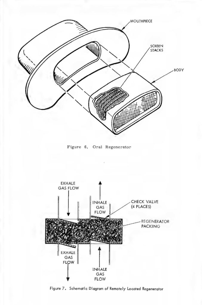
The construction of a thermal regenerator or a mass regenerator is fortunately quite simple.Some typical examples would be layers of screen for a simple thermal regenerator, and this could be implemented into an operational device by wrapping in the shape of a tube as mentioned above. Typically, about 10 layers of 200 mesh screen could serve for a 90%efficient regenerator. An example of how this configuration may be incorporated directly in a diver mouthpiece or face mask is shown in Figure 6. The thickness of this pock is only about one millimeter or 40 thousandths of an inch, and for the 600-90% efficient regenerator example described above, only about 20 watts of heat would be conducted across this very thin surface to a 50°F ambient. Therefore, in the 600′ case, with a respiratory minute volume of one cubic foot per minute, the regenerator would be conserving approximately 210 watts total out of a possible 250 watts. Approximately 20 watts being expended in the 10% inefficiency of the regenerator and the other 20 being conducted through the body of the regenerator. This example is somewhat simplified and idealized for clarity. Actually, the two losses, the inefficiency of the regenerator and the heat conducted through the regenerator are not superposed, but mutually interact and a total sum of approximately 30 watts would be more accurate than the simple arithmetical sum of 40 watts.
Other materials could also be employed for the regenerator. Several methods of construction have been evaluated simply as examples of what is possible and in general it can be stated that for presently existing breathing systems, it is possible to make rather efficient thermal and mass regenerators that can fit within the typically-employed mouthpieces used with these systems. In an operational system the temperature and humidity limits desirable for the working human being are subject to some degree of interpretation and should be tested. As shown by the design equation (8), the relations of overall volume, pressure drop, temperature efficiency and humidity efficiency interact and oil these parameters need to be mutually optimized, to truly optimize the system. Various configurations should be tested with working divers to establish just what degree of efficiency is indeed a desirable value.
Finally, since this device must be used in working systems, the communication device (the microphone), could be integrated with the breathing regenerator. Fortunately, this in itself is not too difficult as task as long as an overall system concept is maintained. The construction of a breathing regenerator is quite similar to a breath shield commonly employed with typical voice microphones, and if the above-mentioned parameters of temperature humidity and pressure drop were tested on an integrated basis with the microphone that the system would be using, the overall combination could be highly useful in a package not much different than the microphones commonly used in advanced systems, with the added advantage of controlling the temperature and humidity in a more or less optimal manner with extremely good breath shielding for the microphone. In conjunction with the testing with the microphone, it should be mentioned that the location of the breathing regenerator is not truly limited to the area immediately adjacent to the human’s mouth, It may be located at some remote position in the breathing system as shown in Figure 7. Here, the normal breathing and check valves are employed to allow the breathing regenerator to be located in a remote part of the system. It is not clear that this would be advantageous or disadvantageous in a typical system, but different types of breathing life support systems might dictate different locations.
SUMMARY AND CONCLUSIONS
A cryogenic processing system can be used to fully revitalize breathing gas by regulating its oxygen content and removing all carbon dioxide on a totally recirculated basis. This configuration has many fail-safe advantages not the least of which is independence from chemical CO2 scrubbers. Its principal bulk, however, is in the stored refrigerant needed to maintain cryogenic temperatures in the face of substantial heat loads attributable to recirculating gases and must accordingly be attended by cryogenic handling equipment.A backpack based upon this design is still quite practical as is seen in the photograph(Figure 8) of one such unit designed for 1,000 foot operation with a duration of 4 to 5 hours. This unit includes a gas circulating mechanism to assist the diver’s breathing during hyperventilation. In the opinion of the author this feature is vitally necessary regardless of how low the breathing resistance through the rig may be. The effort required to overcome the inertia of a massive gas, concentrated by pressure and subject to small,but extremely important, vicissitudes of hydrostatic forces is more than any man can endure for long under even the most ordinary waking conditions underwater.
The cryogenic rig dimensions and weight are still further reducible by suppressing the heat load in four ways:
1. Chemical CO2 scrubbing removes the heat of crystallization.
2. Fractional circulation through the cryogenic processor reduces the regenerative heat burden by the second power due to less than perfect counter-flow heat exchange.
3. Heat and humidity reduction through retention in an oral regenerator
4. Reduced dimensions of the cryogenic components concomitantly mitigates heat leak by conduction and radiation through cryostat insulation and plumbing.
The only modification needed to accomplish this configuration is a shunt line connecting the exhale gas path at a point following chemical CO2 scrubbing to the inhale gas path by means of a passive flow divider which diverts a fixed fraction of the respired gas from the exhale side to the inhale side after the CO2 has been removed. With this change the heat load on the cryogenic portion of the system is so small that cool down and temperature sustaining refrigeration can be supplied simply by means of expanding gas across a Joule-Thomson orifice. This completely eliminates the dependence upon cryogenic support apparatus while retaining most of the cryogenic control features, particularly those concerning oxygen regulation.
Oral regeneration, if correctly designed for conservation of heat and humidity and,perhaps, integrated in a more or less optional manner with a communications systemhas been shown to be of significant value as an aid to diver comfort and a very significantcontributor to increased work efficiency. It is useful for cold underwaterenvironments or hot ones encountered by fire fighters. In effect, it substitutes forones nose when one is forced to breath through his mouth.
In conclusion, the fail-safe features of the basic cryogenic processor which controls all vital life support properties of the breathing medium in an entirely passive and stable manner are largely retained by the rate balanced configuration with the exception of possible failure of the chemical scrubber.
ACKNOWLEDGEMENT
K. W. Cowans, Director of Engineering for Sub-Marine Systems Corporation, has made major contributions to these activities and to a number of related programs currently underway.
REFERENCES
1. Fischel, H., ”Closed Circuit Cryogenic SCUBA” proceedings of the 1970 Symposium –
Equipment for the Working Diver – Battelle Memorial Institute, Columbus, Ohio.
2. SEALAB III – Public announcements and occident reports. Reference Barry Cannon –
Aquanaut – deceased.
3. U.S. Navy Diving Manual, Part I – NAVSHIPS 250-538, Section 1.3.4, para. (12)
“Volumes of Breathing” and Table 1-3 “Oxygen Consumption and RMV at Different
Work Rates”, PP 43-44 January 1959.
4. Cowans, K. W ., Design of Stirling Cycle Machinery, 26 July 1963 – Hughes
Aircraft Company Design Publication.
5. Hausen, H., Tech. Mech. u. Thermodynam., 1,219 (1930)Z. angew. Math. Mech.,
11 , 105 (1931)
6. McAdams, W. H., Heat Transmission – Second Edition McGraw-Hill Book Company,
Inc. New York, Toronto, London (1954)

Therebreathersite was founded by Jan Willem Bech in 1999. After a diving career of many years, he decided to start technical diving in 1999. He immediately noticed that at that time there was almost no website that contained the history of closed breathing systems. The start for the website led to a huge collection that offered about 1,300 pages of information until 2019. In 2019, a fresh start was made with the website now freely available online for everyone. Therebreathersite is a source of information for divers, researchers, technicians and students. I hope you enjoy browsing the content!