
Constant Mass Flow Valves and Orifices theory
I made this page because there were many questions in newsgroups about gas flow through an orifice. Many people are now developing manually operated constant-dosis rebreathers. Jan Jahns has written the article below.
For quite some time I was searching for the exact theory behind the functioning of the Constant Mass Flow System. The technique behind this is very clear to many of you, however, it’s application in real life is something else. If you follow the various new groups on the internet the working of the KISS system and the functioning of a Dolphin injection orifice are subject to discussion. Discussions regarding intermediate pressure for a nozzle/orifice or needle valve are also subject to a lot of confusion.
Jan Jahns is a diver but above all a physicist, having a lot of experience with CMF systems. I have asked him if he had the time to write an explanatory article regarding ‘gassflow through an orifice’. I am therefore delighted that I have now been able to publish this article. Do not be misled by long equations, eventually they are simplified and can be applied more easily. By supplying me with this article, Jan Jahns has built a bridge between science and practice. I therefore would like to thank him for this enormous effort. In the text I added some hyperlinks and some photo’s to further illustrate the text. Jan: thank you very much for this fantastic job!
Mass flow through an orifice
Author: Jan Jahns
2005
Edited: Jan Willem Bech
Menu
Introduction
Amount of gas flowing through an orifice
Measuring the gas flow of mixes
Introduction:
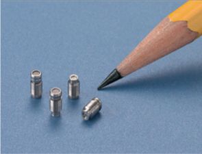
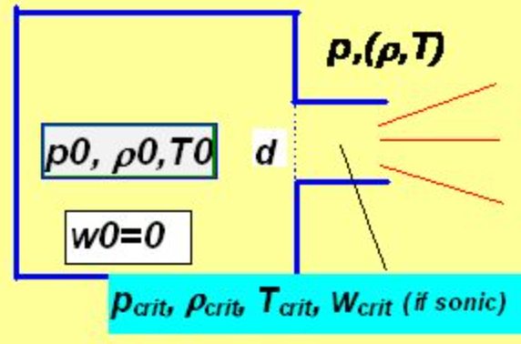
When designing rebreather the problem of estimation of the mass of gas flowing through the orifice (nozzle) of the dosing facilities arises. As such unit a pressure reduction valve mostly serves followed by the nozzle through which the gas flows into space where the ambient pressure reigns. Often double nozzles are used to prevent problems with clogging of one of them. The gas flows obviously from the place of higher pressure p0 to place of a lower one (p1) and during this process expands. This process cannot be described by the commonly used equation of state p.v = R.T, which in principle describe a slow sequention of equilibrium states. Now the process is fast, adiabatic, without sharing heat with the surroundings. In the Ideal Gas approximation (it´s also our case) it could be described by the socalled adiabatic equation
p.vk =const
Here κ is also called Poisson constant given by expression
κ=cp / cv
which states that κ is the ratio of specific heats c measured at constant pressure and constant volume.
The values of κ are specific for each gas and from thermodynamics can be by simple reasoning derived that approximately :
1,67 for monoatomic molecules (e.g. He, Ar)
κ = 1,40 for biatomic ones ( e.g.O2, N2, air, nitrox)
1,33 for tri+atomic (e.g.CO2 …)
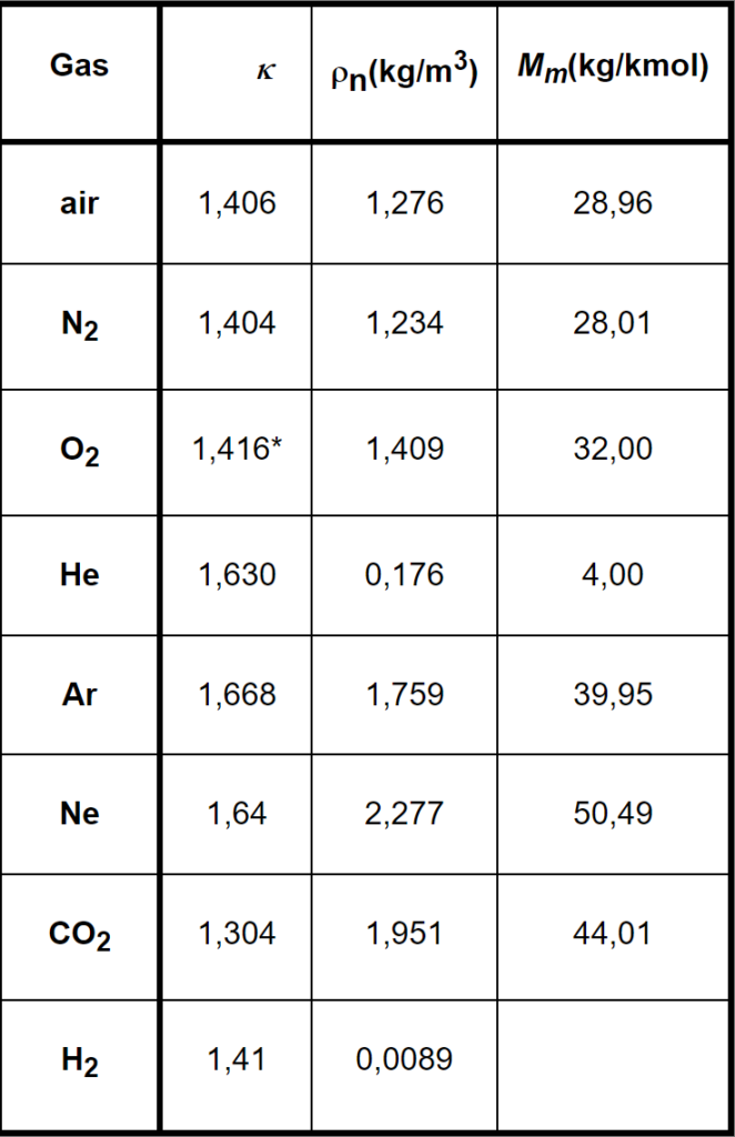
Experimentally estimated data for gases in our interest can be found in the included table together with their densities (specific masses) ρn at normal conditions (temperature 0°C, pressure 1bar =105 Pa) and with their molar masses Mm.
For mixes of gases the relevant values can be obtained by means of the weighted mean values. E.g. the value of κ of Nitrox 32/68 can be calculated as
k = 0,32 . k O2 + 0,68 . k N2 = 0,32 . 1,416 + 0,68 . 1,404 = 1,408
INTERMEZZO: WEIGHTED MEAN VALUE (thanks J.W. Rotteveel)
In this example:
0,32 x κ O2 + 0,68 x κ N2 0,32 x 1,416 + 0,68 x 1,404
κ =———————————————— = ————————————————— = 1,408
0,32 + 0,68 1
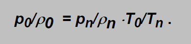
The equation of adiabatic change of state can be also expressed in other form:
ρ0/ρ=( ρ0/ρ)1/ k =(T0/T)1/( k-1)
in which ρ is density and T is the thermodynamic temperature (in kelvins).
Flow velocity:
Consider ideal gas flowing out from a vessel in which its pressure, density and (thermodynamic) temperature are denoted as p0 ,r0 and T0 into the environment of pressure p through an orifice of diameter d as depicted above.
As usually the energy conservation law must be fulfilled expressed in the case of flowing media by the Bernoulli equation. This equation states that in each moment the sum of kinetic and potential energies is constant:
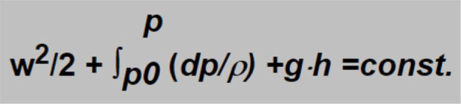
In this equation the first term represents the kinetic energy (w represent velocity), the second and third ones represent the potential energy. In form of integral (second term) the pressure energy is expressed, which is of the main importance for gas in contrary to the third term representing the gravitational energy which concerns much more liquids and can be neglected in the case of gas calculations.
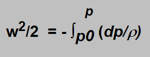
Let us suppose that gas starts flowing from a still state ( which is not exactly true as our reasoning concerns the intermediate pressure space into which the gas flows from the high pressure and moreover a little bit cooled by the expansion. The error introduced by the neglecting of those facts is allowable). Then the constant on the right side of the equation can be put equal zero and we can get
Involving the expression for r from the adiabatic equation and solving the integral we obtain for the gas velocity expression;
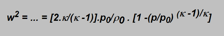
One remark: this expression is usable to calculate flow at „subsonic“ velocity as shall be explained later.
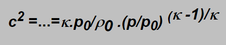
The gas velocity in the narrowest („critical“) place of the nozzle cannot be higher than the local sound velocity. But the sound velocity is given by;
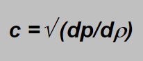
Involving again the r from the adiabatic equation and differentiating we obtain at the end:
Should the flow velocity be sonic (equal the velocity of sound) we have to put w2 =c2 and from equations derived we obtain that for the ratio p/p0 (i.e. for the ratio of the outlet to inlet pressures) following condition has to be fulfilled:
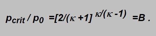
Here pcrit is the critical pressure in the critical section of the nozzle and from the formula follows that if the outlet pressure p is lower or equal to pcrit , i.e. if p/p0 £ B holds in the critical section the local sonic velocity wcrit is achieved which cannot be exceeded by no increase of the inlet pressure p0. The local velocity is emphasized as the temperature differs here from the inlet gas temperature as will be shown later.
Involving the ratio into the formula mentioned above we obtain the critical velocity as:
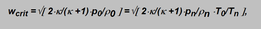
as from the ideal gas state equation applied onto the non expanding gas is:
(Here the subscripts 0 and n denote the relevant variables in the inlet side and in the normal conditions).
inserting e.g. the value of k for biatomic gases gives the value B=0,528.
The values of the inverted ratio p0 /pcrit =1/B lie for the breathing gases in the range 1,90 -2,05, i.e. p0 /pcrit in average aproximately equals 2. It means again that the inlet pressure p0being at least the double of p -the outlet one -the velocity in the nozzle is sonic. But being lower, e.g. p0=1.5 p the velocity would be subsonic.
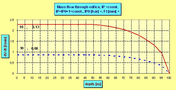
The above reasoning implies following: holding the inlet pressure p0 constant (independent of depth) and equal 10 bars (absolute) the velocity (i.e.also the gas flow as we´ll see later) is sonic up to depth in which the ambient pressure is half of it, i.e. up to 40 meters, in which the ambient pressure is 5 bars. The velocity in the nozzle of airwhose inlet temperature has been 0°C is in each depth up to 5 bars 303 m/s. But going deeper the velocity decreases onto 230 m/s in 60 m according
w =Ö{ [2.k/(k -1)].p0/r0 .[1 -(p/p0) (k -1)/k]} ), onto 105 m/s in 80 m and the flow would stop in 90 m (where ph =10 bar ºp0).
The density and temperature of flowing gas in the nozzle is possible to calculate from the formulae:
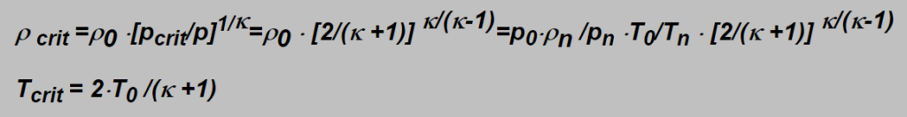
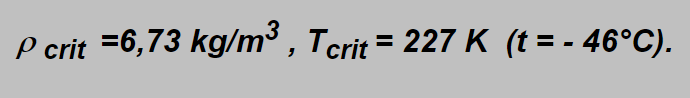
Their values in the example given above are:
Amount of gas flowing through orifice:
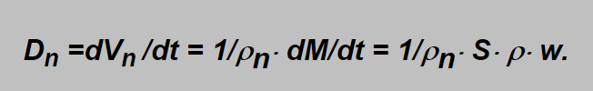
The mass flowing through the orifice in a time unit dM/dt can be calculated as
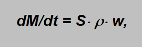
where S denotes the area section of the narrowest part of the nozzle (S =p × d2 /4in the case of circular orifice, d being the orifice diameter) and ρ, w are already known density and velocity in the orifice.
The amount of gas flowing through the orifice is more frequently expressed in term of „normal volume“ units in prescribed time (e.g.normal liters in minute, l/min or lpm). As „normal“ the volume at normal atmospheric presure is ment (i.e. „at the sea level“). This variable, denoted Dn here, can simply be estimated from the mass flow dividing it by the normal density ρn of the gas (Vn =M/ρn ), i.e.:
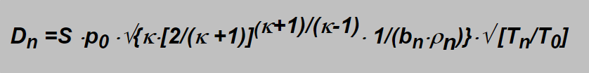
For the sonic flow the critical values ρ krit a wkrit should be inserted giving
In this formula some constants specific for specified gas take place which can be assembled into one constant giving a simple expression:
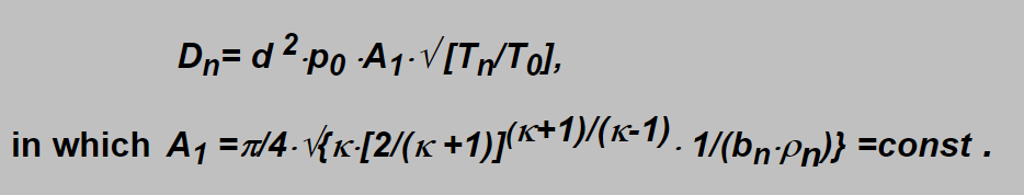
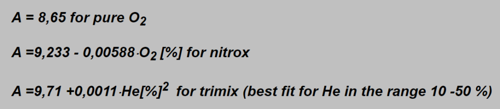
Including into the constant also conversion factors for units to be used (pressure in bar, nozzle diameter in mm and flow in liter pro minute) and neglecting the temperature ratio then constant A can replace the A1 giving the possibility to calculate the flow of commonly used breathing gases in a very simple manner:
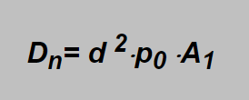
By a simple analysis the following formulae can be found for this constant:
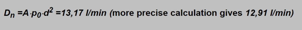
Example: TMX20/50, d =0,31 mm, p0 = 11 bar :
It should be emphasized that the constant was derived for circular smooth orifice what is the shape ensuring the best flow as the ratio of the wall surface to the inner volume is the lowest from all possible orifice shapes. The walls and their quality affect (i.e. slow) the flow of the gas by friction and turbulence. So using an orifice of another shape the flow would be lower, the lowering being expressed by a certain constant known as shape factor.
Rebreather calculations
In calculations made above were as p0 and pambthe intermediate and ambient pressures (in bar) denoted. (p0 =the so called intermediate pressure between the first stage and the flowvalve containing the orifice. pamb is the surrounding water pressure).
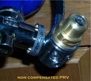
Important: p0isconstant when the pressure reduction valve is not compensated to ambient pressure,
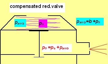
And p0 increases with increasing depth byh[m]/10 when compensated (as in common regulator).
Example: The intermediate pressure p0 of a compensated regulator messures 9 bar on the surface shown on the IP gauge. If a depth compensated (normal) first stage is used the gauge will show 12 bar @ 20 mtr depth.
Example: The intermediate pressure p0 of a non-compensated regulator messures 9 bar on the surface shown on the IP gauge. If a depth non-compensated (adapted) first stage is used the gauge will show 9 bar @ 20 mtr depth and stays 9 bar also when going deeper.
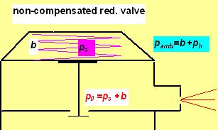
In this picture b represent the normal atmospheric pressure (1 bar usually), ps the pressure exerted by the spring force (in fact the gauge IP) and ph the hydrostatic pressure. pamb is for the ambient pressure (absolute).
The non-compensated pressure reduction valve (PRV) is designed for constant mass flow applications, i.e.:
- for gaining constant dose of diluent in CMF SCCR (e.g. Dolphin)
- for gaining constant dose of oxygen in MCCCR (manually controlled CCR -e.g. KISS)
So the maximum allowed depth is this one, in which the sonic flow is maintained, i.e. in which the ambient pressure pamb is roughly equal the half of intermediate pressure p0. In deeper depths the flow becomes subsonic and the mass flow decreases as the depth increases.
Example1: if p0 =11 bar then the maximum allowed depth (in which the flow becomes subsonic) lies in about 45 meters (pamb =5.5 bar).
Example2: with p0 =11 bar and orifice diameter d =0,08 mm the flow of pure oxygen is 0,61 lpm in each depth up to about 45 m, but in depth of 90 m the subsonic flow gains only 0,36 lpm ! To be usable to 90 m you need p0 ³ 20 bar. But then the orifice must be smaller to restrict the flow which would reach 1,1 lpm using the original one. You have to choose 0,06 mm to gain 0,62 lpm or 0,07 mm to gain 0,85
In compensated pressure reduction valve (the same as the 1st stage of common regulators) with growing depth increases also the intermediate pressure. From reasonings given above we know that higher p0results also in greater flow (remembering Dn =A×p0×d2 ?). Denoting p00 the (absolute) intermediate pressure at surface and p0hthe IP in the depth h (h in meters), then p0h = p00 + h/10( p in bars).
The gas dose Dh in depth is given by the surface dose D0 multiplicated by the ratio of intermediate pressures in the depth to the surface one,
i.e. by p0h/ p00 ,hence
Dh =D0 · p0h/ p00 = D0 · (p00 +h/10) / p00 = D0 · (ps +b +h/10) / (ps +b)
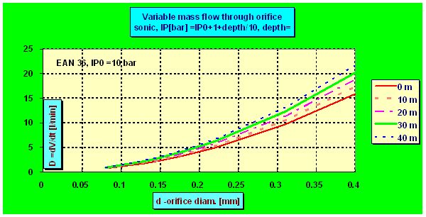
and the dose grows linearly with the depth. But in certain depth hcrit -given by the constant B -the ambient pressure becomes critical compared to the pressure p0h
and the flow ceases to be sonic. Although the flow always increase with deeper depth the increment is no more linear as can be seen in the following plot in which for the sake of demonstration the ps =IP0 =6 bar was chosen and flow through two nozzles each of diameter 0.2 mm was calculated :
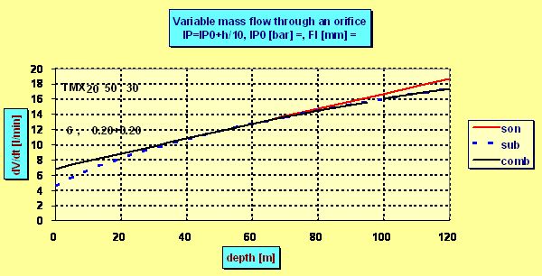
The mentioned critical depth can be easily found as in this depth the intermediate pressure p0h must be roughly 2 times greater than the ambient pressure pamb , i.e. ps + pamb =2× pamb . That means that the flow ceased to be sonic in the depth in which the ambient pressure pamb equals the „spring pressure“ ps which in fact is the (over-)pressure measured by an IP gauge. E.g. having ps =10 bar, the flow becomes subsonic in 90 m, where pamb = 10 bar. But even in 200 m the actual dose is only 5% lower than the flow predicted by the linear equation as although the velocity drops onto only half of the sonic velocity the pressure increment increases the density r0 and so also the flow.
What are the advantages and disadvantages of both arrangements ?
The advantage of the non-compensated PRV is maintaining the constant mass flow in the range of proper depths. So also the estimated dose D of the supply mix is constant and according the well-known equilibrium equation of SCC
fiO2 =( fsO2 × D -SO2 )/( D -SO2 ), *)
(here fsO2 being the fraction of O2 in the supply mix and SO2 the oxygen consumption rate of the diver) also the calculated fraction of oxygen in counterlung fiO2 remains constant. Choosing the IP reasonably high and of course choosing also the proper nozzle the flow ensures fiO2 staying in proper, i.e. safe margins. Also the fractions of other constituents of the inhaled mix (N2, He) can be calculated and used for decompression purposes. Having the p0 chosen as 18 bar, the constant flow of the mix is ensured up to about 80 meters. (But diving deeper then about 40 m trimix or heliox should be employed). The same dose in any depth enables also precise prediction of the supply gas consumption
Regarding the KISS and its clones -the constant sub metabolic dose of oxygen must be inevitably kept in each intended diving depth and so the non-compensated PRV has to be used in the dosing system. As the dose required is small (less then 1 lpm) the orifice area section should be also small as explained in the example 2 above. So to prevent the clogging of such tiny orifice a 10-20 microns filter has to be inserted into the flow path before entering the orifice. Using metering valve instead of circular orifice can improve the situation as eventual clogging would occur only in a part of the flow-through section. But I´m not sure how outer temperature differences affect the flow in the valve.
Employing the compensated PRV in the SCR results in doses Dh depending on the depths. As disadvantage only the not-so-precisely predictable and higher gas consumption could be considered. On the other hand the enhanced flow „improves“ the oxygen fraction fiO2 in the inspired mix, i.e. the fiO2 draws nearer and faster to the supply fraction fsO2 compared to the steady flow. So the estimation of fiO2 can always be made by the help of the above equilibrium equation using the surface dose D0 and taking into account the fact that the calculated value of fiO2 is only a little bit underestimated. Moreover the flow is maintained to be sonic much deeper as shown above and even subsonic flow ensures doses large enough. So the use of much deeper depth of the system is enabled. To estimate the gas consumption during the dive simply the consumption in the greatest depth should be done according the formula
Dh =D0 · p0h/ p00 = D0 · (p00 +h/10) / p00 = D0 · (ps +b +h/10) / (ps +b)
given also above. Remember only, that ps is the IP measured, b =1 (bar) and
D0 is the surface dose. Estimation of the flow is the last topic discussed here.
*) BTW the fiO2 is higher then calculated here using separated exhale bellow (as is common) giving also piO2 higher by about 5 kPa (0,05 bar) in any depth.
Measuring the gas flow of mixes
To estimate the flow of gases mostly the float (e.g. ball) flow meter is used.
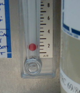
The flowmeters are calibrated for certain gases or their exactly definited mixes -oxygen, air, nitrox 32/68 etc. In the need to employ the flowmeter for another mix, e.g. for trimix, the following considerations could be made:
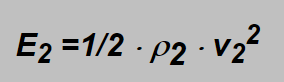
The force F1 holding the float in certain position (marked as a certain flow) in the gravitational field is proportional to the kinetic energy of the flowing gas
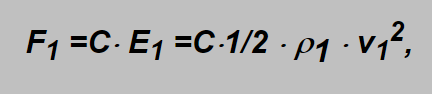
in which formula the subscripts „1“ concern the original gas flowmeter is designed for and C is the constant proportionality factor (incl. shape factor of the float). The mark on the pipe concerns the flow velocity v1 of the specified gas. If another gas flows through the flowmeter then its energy is
and on the same mark also the energies of both gases should be the same:
Inserting here the above mentioned formulae the following expression can be obtained:
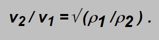
i.e. the ratio of the gas velocities is inversely proportional to square root of their densities. Densities are proportional to molar masses Mm of the gases which could be easier found then densities themselves and as the flow D is proportional to the velocity the expression for flows of the gases can be written as
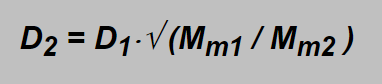
As said in the introduction part for mixes of gases the relevant values can be obtained by means of the weighted mean values. E.g. the value of Mm1 of air (21 % O2, 79 % N2) can be calculated (using table in the introduction part) as
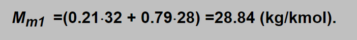
Wishing to use air flowmeter to measure flow of trimix TMX 20/50 (20 % O2 , 50 % He and 30 % N2), then
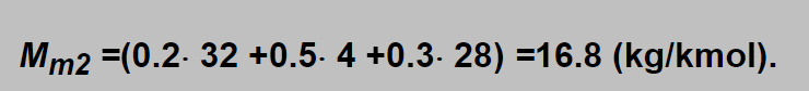
Inserting obtained values into the square root : √ (Mm1 / Mm2 ) =√ (28.8 / 16.8) =1.31 and e.g. with the float on the 10 l/min label (D1=10 l/min) the actual flow of trimix is D2 =13.1 l/min. Using oxygen flowmeter the label 10 l/min denotes 10×√ (32.0 / 16.8) =13.8 l/min.
Units
UNITS
P= pressure
V= volume
R= gasconstant [8,314 J mol-1 K-1]
T= temperature in Kelvin
Kelvin = Celsius + 273.15 // Fahrenheit =( Celsius/(5/9)) + 32
k =cp / cv= poisson constant
Mm = molar mass
p0 = pressure before orifice
r0 = density before orifice
T0 = temperature in Kelvin before orifice
Tn = normal temperature in Kelvin
Tcrit = critical temperature in Kelvin
W = velocity
Wcrit =critical velocity
g = acceleration at surface due to Earth’s gravity= 9.8 m/s2
h = height above ground
c = characteristic speed
pcrit = critical pressure
pamb = ambient pressure
r = density
rkrit = critical density
rn = normal density
B =ratio of the outlet to inlet pressures
S =area section of the narrowest part of the nozzle (S=p × d2 /4)
d = orifice diameter
A = constant
B = constant
PRV = pressure reduction valve
CMF = constant mass flow
MCCCR = manual controlled closed circuit rebreather
IP = intermediate pressure
p00 = absolute intermediate pressure at the surface (=ps+b)
p0h = intermediate pressure at certain depth (=ps+pamb)
D = gas dose in normal (surface) liters per minute
Dh = gas dosis produced by IP at certain depth h
D0 = gas dosis measured at the surface (open PRV)
Dn = gasflow through orifice
Safety check
Jan Jahns , thank you for your fantastic help by writing this article for my web!

Therebreathersite was founded by Jan Willem Bech in 1999. After a diving career of many years, he decided to start technical diving in 1999. He immediately noticed that at that time there was almost no website that contained the history of closed breathing systems. The start for the website led to a huge collection that offered about 1,300 pages of information until 2019. In 2019, a fresh start was made with the website now freely available online for everyone. Therebreathersite is a source of information for divers, researchers, technicians and students. I hope you enjoy browsing the content!