

The tethered diving rig of Sealab II
OK, and now something completely different. One of the units used for deep diving in the 60’s is called the Tethered Arawak system. It is a pleasure to offer this information to my readers. The Arawak system is a incredible high tech system when the depth involved taken in perspective. The system is used for depth up to 500 meters. Later models like the SLS system and the BOSS system are improved models of this innovative technology. This system was originally designed by Westinghouse and was used by the Aquanauts of Sealab II.
In the proceedings from the International Workshop in Ballatar Scotland, held 1-4 November 1991 E. Flook and V. Brubakk write in great detail the working of the Arawak 6 system. The information was kindly provided by S. Readey For which I am very grateful to her.
Lung Physiology and Diver’s Breathing Apparatus. Eds. Flook, V., Brubakk,A.0. Proceedings from the International Workshop, Ballater, Scotland, 1st – 4th November 1991.SINTEF UNIMED, Aberdeen 1992.
DEVELOPMENT OF AN AUTONOMOUS 15 MINUTE BAILOUT CAPABILITY
FOR USE UP TO 500 MSW.
S.D. REIMERS, *W.J. O’NEILL, B.D. TICE and M.K VA MME
Reimers Engineering Inc., 6314-K Gravel Avenue, Alexandria, VA 22310, USA. *O’Neill & Associates
Summary
The purpose of this project was to develop an integrated diver’s breathing apparatus for use down to 500 msw with a fifteen minute autonomous bailout. The primary purpose of this paper is to introduce the Arawak Six bailout system to the diving community. Therefore the bailout system is the main focus.
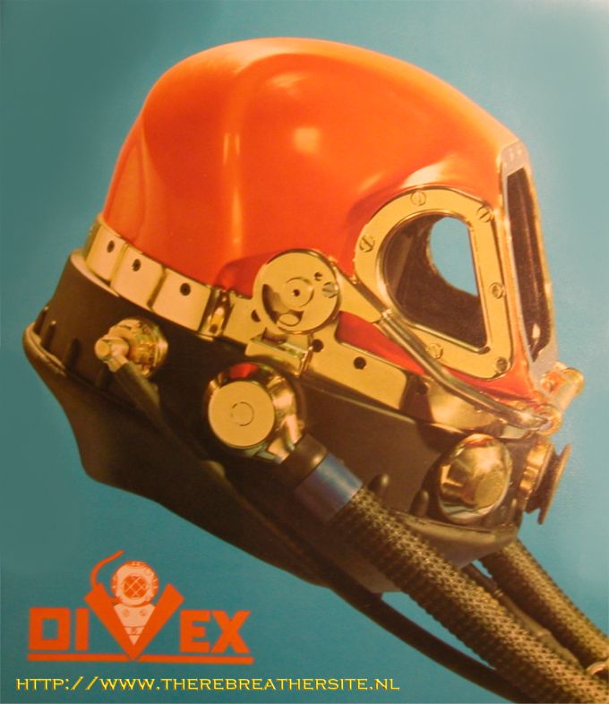
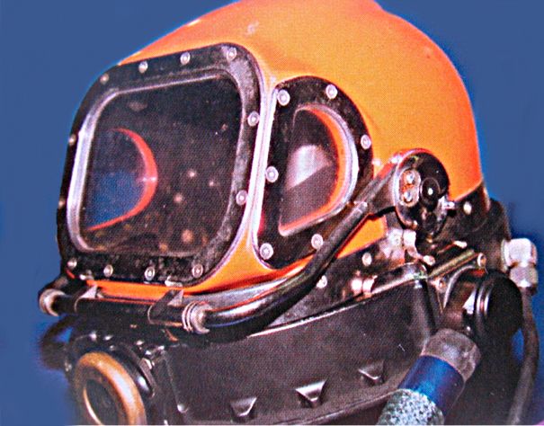
This bailout system is part of a bigger package which forms the Arawak Six. This system includes the diver’s helmet, supply and return pumps, pressure and flow controls, diver’s umbilical and other related items. Some of the parts of this system have been in existence for several years, most notably the Arawak helmet and flow controls. These items have been refined in this development and built upon for the Arawak Six system.
The most prominent feature of the Arawak Six bailout system is that the CO2 absorbent canister is located inside the helmet. When the diver goes on bailout, he breathes directly into the canister through a short tube running up to the canister in the front of the helmet. The Arawak helmet has a fairly large neckdam compared to other helmets and this neckdam acts as a counterlung in the bailout mode. The metabolic oxygen make up is provided by a gas bottle on the diver’s backpack. The oxygen make up system works similar to other semi closed circuit rebreathers in that the gas containing the oxygen (litre flow) is flowed steadily into the circuit. The complete bailout breathing circuit is fairly simple. This simplicity is a vital attribute of commercial diving equipment.
The project Team
This development was initiated by British Petroleum Norway, Ltd. U.A. in 1988. The team of Reimers Engineering (REI) and W. Jerry O’Neill were employed to develop the system. REI has had about 20 years experience in engineering and testing of diving and hyperbaric equipment. Jerry O’Neill has long been a designer of diving equipment with many successful designs to his credit.
The arawak Concept
The Arawak was originally conceived by Jerry O’Neill to be a return line system which would use bell gas to supply the diver and thus eliminate much topside equipment associated with conventional return line systems. The principle is that the bell gas must be monitored and controlled, so why not use that gas to supply the diver. This
system uses a circulating pump assembly mounted on the bell to drive the breathing gas to and from the diver.
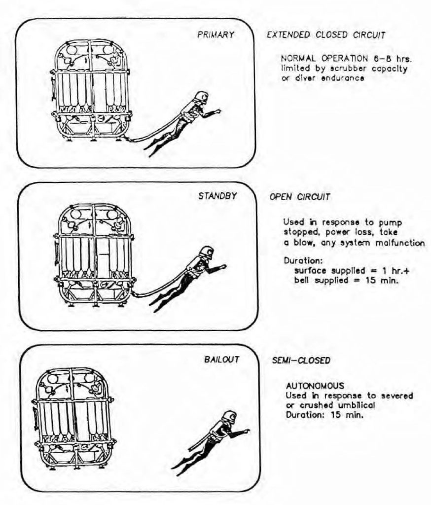
The Arawak Six has three modes of operation, they are: Primary, Standby and Bailout. These modes are shown on figure 1. The primary mode is normally used and the other modes are used if there is some sort of system malfunction.
Equipment
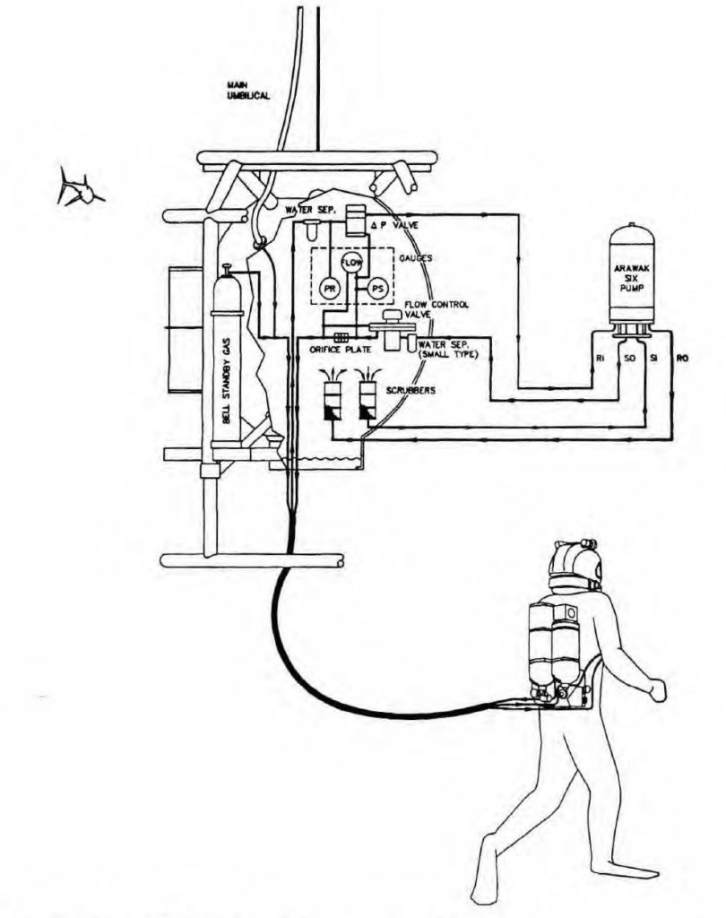
The complete system consists of the following equipment. See figure 2 for details:
Diver worn equipment including:
- Helmet with integral gas heater, bailout canister and fitted liner.
- Backpack including bailout bottles and backpressure regulator (BPR)
- Harness assembly
- Bailout control block
- Hot water splitter block
Diver’s umbilical
Bell flow and pressure controls including:
- Supply flow control valve
- Supp1y flow control orifice
(for sensing flowrate) - Return flow, pressure control valve
- Supply and return CO2 scrubbers
- Supply and return water separators
Bell mounted circulation pumps:
- Supply and return
Topside controls including:
- Pump motor controller and monitors
Normal system operation:
In the normal mode, the Arawak Six helmet works similar to a free flow helmet but the return gas flow is throttled to maintain proper helmet pressure. The supply flow to the helmet is controlled in the bell, at rates between 98 and 127 alpm (ambient litres per minute),
The normal mode system has been thoroughly tested both by breathing machines and
in manned testing and found to work quite well. Work of breathing and inspired CO2 levels are well below the recommendations in the NPD guidelines (I).
Standby system operation:
The standby gas supply system is actuated by a chest located hand valve. This valve is easily accessible by either gloved hand. When opened, this valve admits a steady flow of approximately 85 alpm to the helmet valve ring. This circuit is completely separate from the primary system up to the point where gas enters the valve ring. The 85 alpm flow is adequate for moderate work rates until the diver can return to the bell or the operation is otherwise concluded.
Bailout system operation:
The Arawak Six includes an autonomous bailout system designed to work at any depth from 0 to 500 msw for a minimum of 15 minutes. The principal components of the bailout system are the following: See figure 3.
- Fold-away mouthpiece and CO2 absorbent canister, completely contained within the protective envelope of the helmet.
- Backpack containing gas bottles and pressure regulators.
- Front mounted control block containing the valves necessary to initiate and control the bailout gas services.
The inclusion of the breathing circuit parts (mouthpiece, ductwork and CO2 absorbent canister) completely within the protective envelope of the helmet allows the system to be relatively simple as well as minimizing external bulk and complexity.
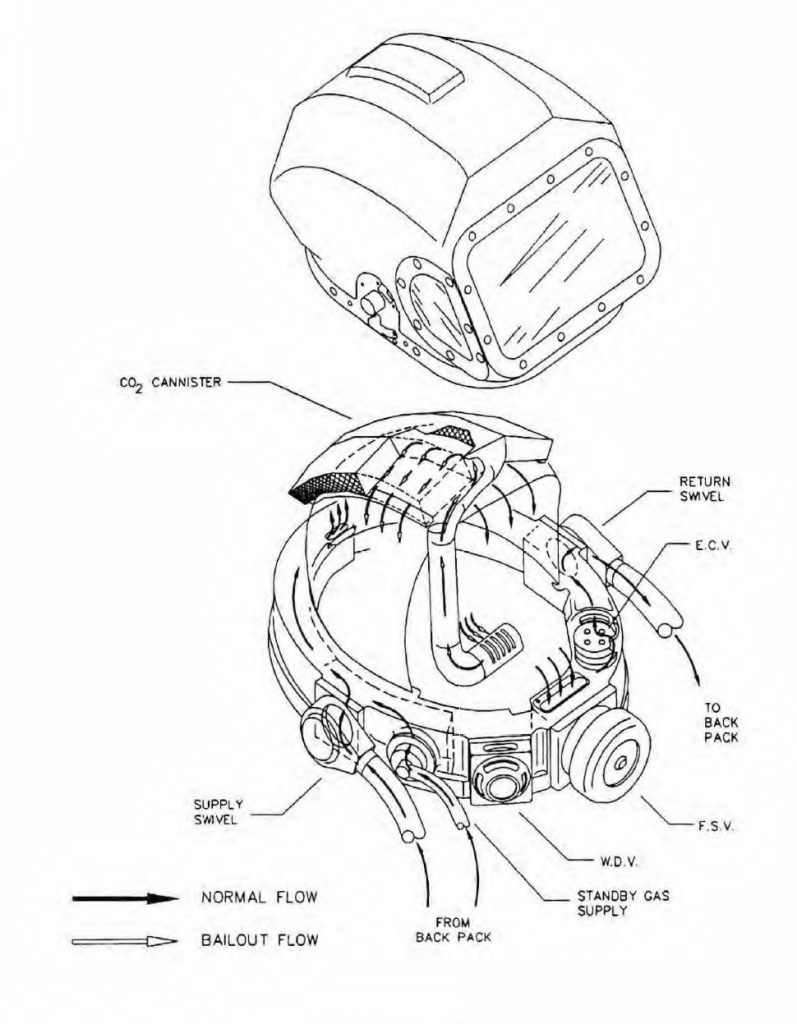
It also permits very good heat retention in the respiratory circuit without the need for hot water hoses or other forms of supplemental heat in the bailout system. See figure 4.
Once actuated, the bailout operates similar to other semi-closed circuits. The two main differences are as follows:
- Two different gas supplies are used. One gas supply is for the “litre flow” formetabolic oxygen makeup. The second gas supply is used for volume make-up to the helmet-lung circuit.
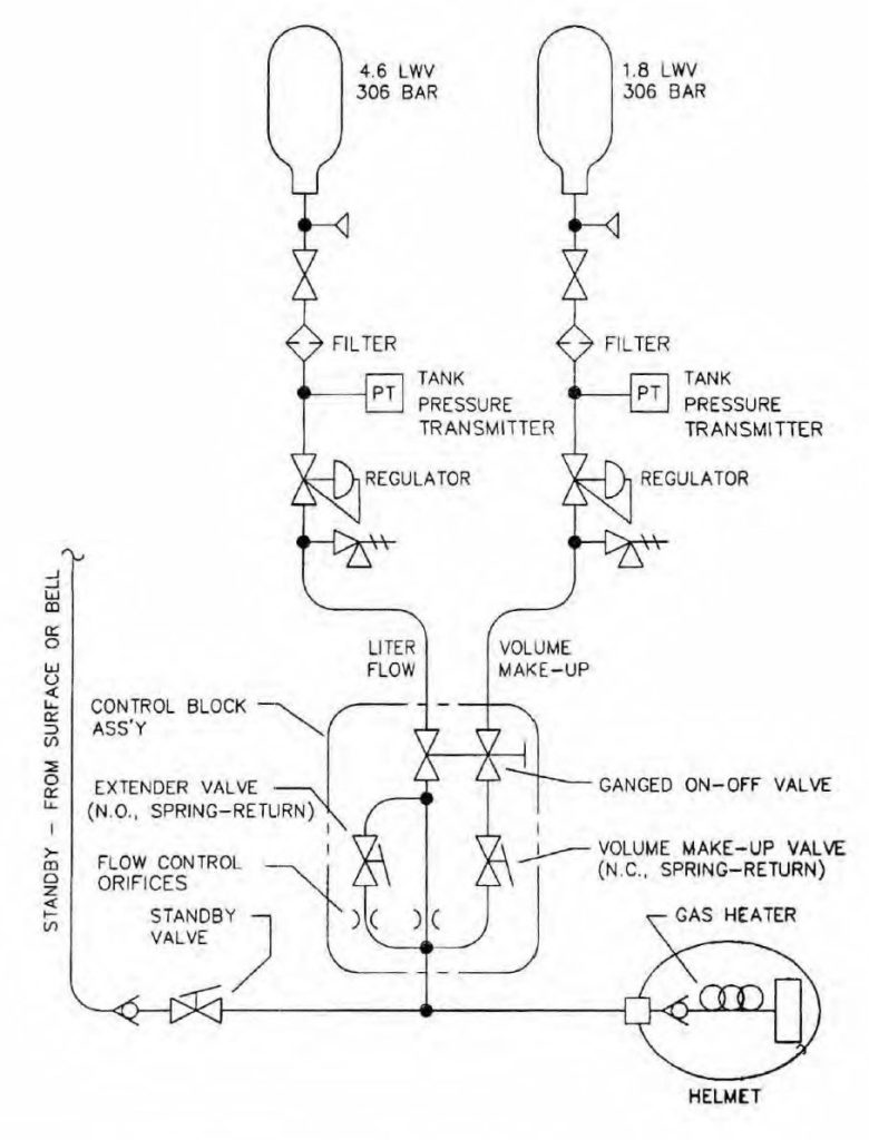
- The other difference is that on this system, litre flow is controlled by a constant pressure drop through control orifices, instead of using a constant absolute pressure (regardless of depth) upstream of the control orifices. This is shown on figure 3. This arrangement allows the flow control system to work over a great depth range while keeping the size of the litre flow bottle as small as possible.
Bailout System Features:
Having the breathing gas circuit completely enclosed in the helmet permits the following features:
- The bailout circuit contains a minimum number of components, which leads to reliability and lower cost.
- The scrubber is in a position where it is well protected ‘from undetected flooding and other forms of accidental damage.
- The normal supply gas flow passes under the scrubber, keeping it warm and ready for use. See figure 4.
- The scrubber is protected from heat loss to the sea by its location inside the insulated helmet shell.
- This arrangement allows short and simple interconnecting tubing which makes work of breathing low.
- Using the helmet neckdam as the counter lung makes the breathing characteristics (hydrostatics) fairly consistent with diver orientation compared to systems with external counterlungs. The compliant volume of the bailout circuit is about 2.5 litres. The bailout compliant volume can be increased by increasing the size of the neckdam, but this causes an increased inspired CO2 level in the normal mode of operation. The project team decided to not sacrifice the excellent normal mode performance to increase the bailout compliant volume.
- The absorbent is protected from degradation due to CO2 migration by its location which is well removed from the diver’s facial area.
- The mouth tube for the bailout system normally resides in a retracted position in the front of the diver’s right cheek.
Bailout Gas Supply Circuit:
The gas supply circuit contains a “litre flow” (02 make-up gas) supply and a volume make up supply. The volume make up gas is used to insure that the circuit has sufficient gas to allow comfortable breathing.
The volume make up bottle contains enough gas to fill the neckdam two times at 500 msw or more at shallower depths. This gas will be basically the same mixture as the gas being used in the normal mode.
The litre flow supply is used to supply the gas required for metabolic oxygen make-up. The litre flow bottle contains enough gas to supply the active diver for fifteen minutes and the inactive diver for up to thirty minutes. See figure 5. The inactive diver can extend the litre flow duration by holding a valve on the bailout control block on his chest. Holding this valve (extender valve) doesn’t stop the flow, it simply reduces it.
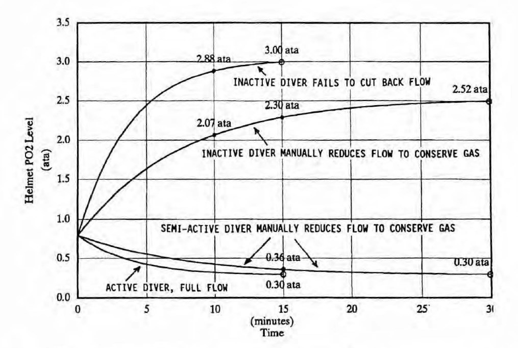
(RMV 37.5 1/min), “active” oxygen consumption 3.01/min (RMV 75 1/min).
The flow rate of litre flow gas is controlled by flow two small orifices (Lee jets). The flow rate is set by the diver, before donning the equipment. The basic procedure is to attach a flowmeter to the bailout/standby supply hose outlet. The flow is then started by opening the “start” valve on the flow control block. While watching the flowmeter, the flow is adjusted, by adjusting the pressure regulator on the litre flow bottle. The pressure regulator used is a standard SCUBA first stage with an external adjusting screw. This method of adjustment gives proper flow rates throughout the excursion range of 10 msw above to 30 msw below the bell. The proper flow rates are given on a table in the operating manual.
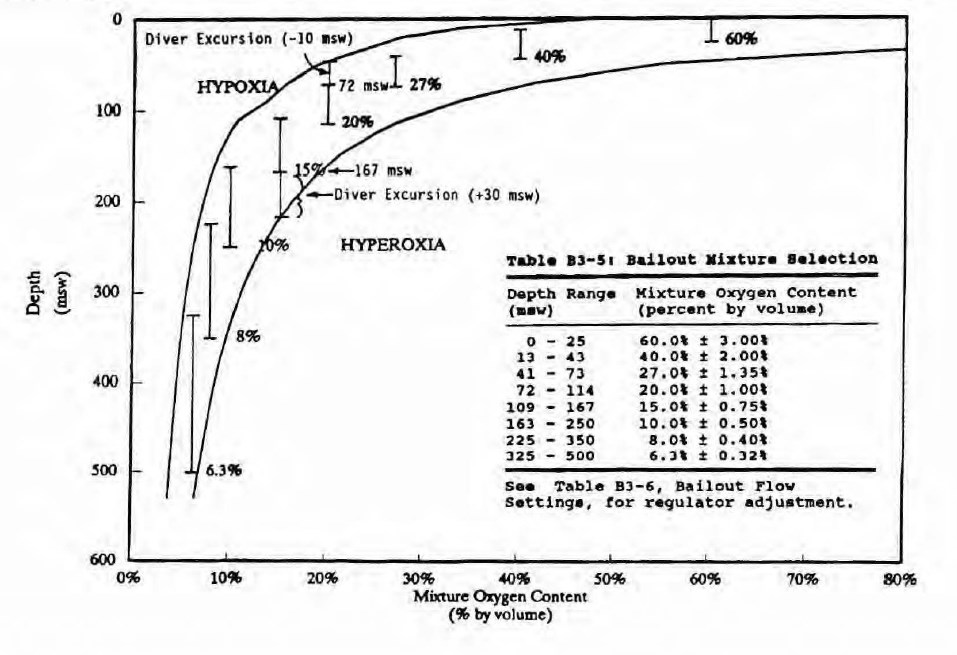
The litre flow gas is a mixture of oxygen and helium. The mixture to be used is determined by the working depth. as shown in figure 6. These mixtures were calculated by knowing the normal (not extended) flow rate of the gas, and adjusting the 02 percentage as required to maintain the PPO2 level in the range shown on figure 5. For depths of 305 to 500 msw, the normal flow rate was determined as the largest flow rate that will last the full fifteen minutes for each depth. For shallower depths, the full flow rate is the highest, repeatable flow that the circuit will produce. In all cases the flow is maximized because this makes the PO2 levels more stable than with a lower flow.
Switching to Bailout:
To switch from the normal mode breathing to bailout mode, the diver must complete two actions. The first is to open the start valve on the chest mounted bailout flow control block. The start valve has a large handle that is turned 1/4 turn to align with the bailout hose to start flow. This will start the flow at the normal rate. The second action is to move the bailout mouth tube to the front of the divers mouth. This is done by rotating an external handle under the helmet face plate. This allows the diver to breath into the absorbent canister.
Once these actions are completed, the diver is effectively on bailout. The next action that is required is to close the fail safe valve (FSV). This is done by turning and pushing in on the large knurled ring on the front of the helmet (figure 4). This action closes off the helmet exhaust duct and keeps gas from escaping. At this point the system compliant volume can initially be limited to about one litre until the diver adds some makeup gas. This is done by pushing the make up valve on the flow control block. If the diver decides that he can tolerate an initial one litre tidal volume, he can conserve makeup gas by waiting for the litre flow gas to fill the neckdam. The litre flow will fill the neckdam in a few minutes or less depending on the depth.
When the diver is comfortably on bailout, he can press the extender valve on the flow control block. This reduces the litre flow and permits bailout duration to exceed 15 minutes. This requires the diver to be inactive or semi-active (see figure 5) thus having a low 02 consumption.
Figure 5 shows the high and low PP02 levels attainable if the diver makes inaccurate judgments regarding his work level. These levels are considered safe for the short exposures that may be encountered in the bailout mode (3).
It should be stressed that figure 5 is simply the design conditions for the bailout gas supply system. The high and low P02 levels shown on figure 5 are a worst case
scenario. This means that these extreme P02 levels are possible if all of the control tolerances stack up in a favorable manner. An example of this is as follows (see figures 5 and 6): With the bell at 167 msw and the diver at 30 msw below the bell, the helmet
P02 can reach 3.0 ata in fifteen minutes if all of the following conditions are met:
- The diver is inactive (0.6 standard litres per minute,02 consumption)
- The diver fails to use the extender valve
- The litre flow gas is 15.0 + 0.75% 02 (high tolerance limit)
- The litre flow rate is at the high tolerance limit
- The diver stays at this depth for the full 15 minutes.
Another example shows how the lower P02 level could be reached. With the bell at 72 msw and the diver on an upward excursion of 10 msw, the P02 could reach 0.30 ata if:
- The diver is active (3.0 standard litres per minute, 02 consumption)
- The litre flow gas is 20.0 – 1.0% O2 (low tolerance limit)
- The litre flow rate is at the low tolerance limit.
- The diver stays at this depth for the full 15 minutes.
As one can see from the figures, any type of scenario that could cause an extreme PO2 on bailout has to be considered very unlikely. Most of the time the bailout PO2 level will be closer to the initial level. Also, most saturation diving operations do not use the extreme excursions that this system is designed for. With proper planning by the dive supervisor, these high and low PO2 levels can easily be avoided.
Note that the allowable excursions for the Arawak Six. are 10 msw above and 30 msw below the bell, at bell depths greater than 60 msw. The allowable excursions decrease with bell depth at bell depths less than 60 msw. The excursions are limited by the pump capacity. However, the bailout gas mixtures are selected such that these excursions should not be exceeded in the bailout mode.
Bailout System Performance:
CO2 scrubbing
Extensive testing of the first diveable prototype has shown that the CO2 scrubbing capability of the circuit is very good at depths down to 60 msw. At these depths, the
inspired CO2 levels are comfortably below the target of 2.0 kPa with work rates up to 75 IRMV. At greater depths, the scrubbing capability falls off such that the 2.0 kPa
level is reached much faster.
Although inspired CO2 levels greater than 2.0 kPa are not unreasonable in a bailout situation (2), we are planning to increase the size of the absorbent canister by about 28%. One atmosphere testing with various sized canisters indicates that this increase in the volume will increase canister duration greater than a linear increase proportional
to the size increase. This is because the canister’s efficiency also increases with its size. The new canister is expected to maintain inspired CO2 levels below 2.0 kPa for 15 minutes at all depths up to 500 msw and continuous work rates up to 62.5 IRMV. Our tests have also shown that an absorbent canister that will meet these parameters, will last at least 25 minutes at lower work rates.
Bailout Work of Breathing:
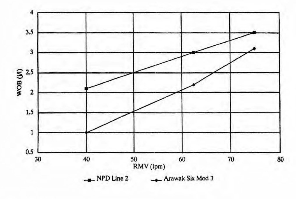
The bailout circuit work of breathing has been refined in extensive testing and development work. This work has shown that the work of breathing is predictable with a simple computer model. This model considers flow resistive loads that increase with gas density and elastic loads from the counter lung (neckdam) which are fairly constant. With the new canister being developed, the work of breathing is predicted to be as shown on figure 7. The NPD guidelines have no requirement for bailout work of breathing, so we have chosen line 2 of the NPD guidelines (l) as a design target. The Arawak Six will meet this requirement with some margin.
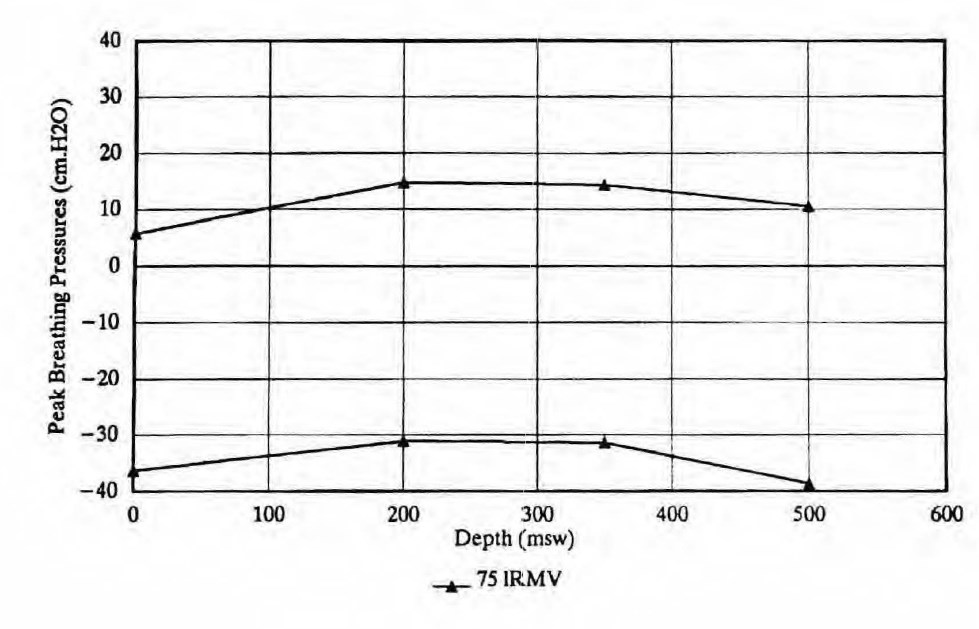
The bailout mode peak breathing pressures have been determined in our testing for several depths. These data are shown on figure 8. At 75 IRMV the inhalation are somewhat high when referenced to the “reference” (Pr) or relaxation pressure as suggested in the NPD guidelines. Note that the Pr is shown as the zero line on figure 8. These pressure peaks are caused by having a relatively low compliant volume in the bailout circuit. These peak pressures could be improved by enlarging the neckdam, but as stated before, the project team has chosen to not sacrifice normal mode performance by doing this. The inhalation peak pressures are much better at lower work rates.
Gas Flow Testing:
The gas flow circuit for the litre flow gas has been tested at several depths up to 500 msw and found to deliver steady and repeatable flows. This circuit is expected to be very reliable, especially because the flow will be set before each dive.
Future Manned Testing:
The Arawak Six system, has been thoroughly man tested in shallow water both at REI and other locations. The normal, standby and bailout systems have been found to work well and have been well received by the many different divers using it.
The normal and standby systems are simply refined versions of the Arawak V systems. The Arawak V was thoroughly man tested in the early 1980’s by several different parties. For this reason, there is little uncertainty about the deep, manned performance of the normal and standby systems of the Arawak Six. However, at this writing, the bailout system has not been man tested more than about 3 msw. Therefore the plan is to do instrumented, manned testing of the bailout system in the near
future. This testing will attempt to confirm the PO2 control and CO2 scrubbing capability of the system at as many different depths and work rates as practical. It is also planned to check the diver’s acceptance of the compliant volume of the bailout system.
Conclusion:
The Arawak has developed over many years to be a very refined diver’s breathing apparatus. With this recent work, the bailout system has been well integrated into the package. Extensive testing and development has shown that the new parts of the system are very workable.
The intent of this development was to make a completely integrated breathing apparatus, in which all the pieces would work well together and thus make the diver safer and more productive. Throughout this development the project team has tried to keep the system hardware simple, for many obvious reasons. We are well on the way to achieving those goals.
References:
1.Norwegian Petroleum Directorate, Guidelines for Evaluation of Breathing Apparatus for use in Manned Underwater Operations in the Petroleum Activities, 1991
2.Hamilton, R.W., Carbon Dioxide: The Real Hazards, Technical Paper, 1991
3.Hamilton, R.W., Recommended Oxygen Levels for Arawak in Bailout Mode, Memo to S.D. Reimers, September 17, 1991
In the following article, the operation and application of the arawak system is described in a more general manner by Penzias and Goodman dd 1973
General Description: (Penzias & Goodman 1973)
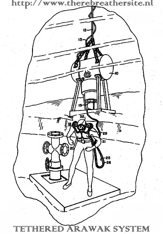
The Tethered ARAWAK Sytem
This apparatus is used for lateral, and limited vertical, excursions from subsurface diving bases. Supply and vacuum pumps (compressor-depressor), situated inside the diving habitat, provide chamber gas to the diver and, via a second hose, return it to the habitat for carbon dioxide removal and processing with the atmospheric purification equipment located there. The Arawak gas circuit constitutes a satellite appendage of the subsurface base: it is a rebreathing apparatus without carbon dioxide removal capability, and is a closed-circuit mixed-gas apparatus without self-monitoring devices or automated mixture control. The compensatory advantages which this system provides include the following: simplicity of predive preparation, diver monitoring, and post-dive maintenance; economy in procedurement and operational costs; augmentation of diver safety, conferred both by restrictions implicitly imposed with a tether, as well as by engineering features already mentioned.
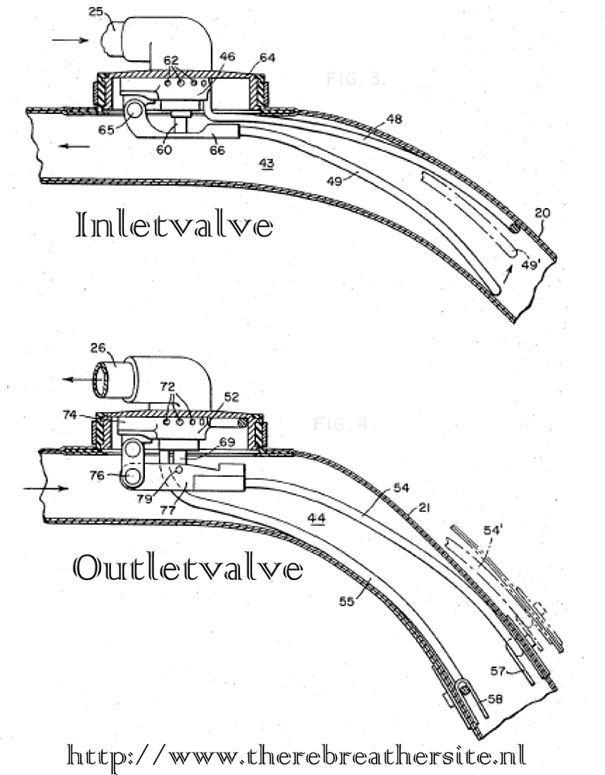
Abstract,
The Diver apparatus includes an inhalation breathing bag and an exhalation breathing bag with a breathable gas mixture being supplied by pressure source to the inhalation bag through the inlet valve. The exhalation bag is connected to a suction source through an outlet valve with the apparatus including a flexible hose connected between the breathing bags and having a suitable mouthpiece and valving arrangement for diver breathing. The inlet valve opens up to supply the gas mixture when the inhalation breathing bag collapses due to a diver inhalation or a descent, and the outlet valve opens to allow removal of the exhaled breath when the exhalation breathing bag expands due to an exhalation or an ascent. One valving arrangement utilizes wire bales extending within the respective breathing bags an another arrangement utilizes valve chambers with diaphragms having on one side the water pressure and on the other side either the inhalation breathing bag pressure or the exhalation breathing bag pressure. The valves are biased to insure that they are not simultaneously opened.
History of development.
The Arawak system is designed by Wilbur J. O’Neill assignor of Westinghouse Electric Corporation, Pittsburg. The equipment is sold by Emerson and later by Reimers Engineering. Finally Divex UK bought the Arawak system.
Wanted information:
The Arawak system has different appearances and had different versions and names. There are Arawak I,II and III systems, and also an Arawak Dolphin 7 system. Any additional information on this system is highly desirable and also very important to record historically. Please send any information at your disposal.
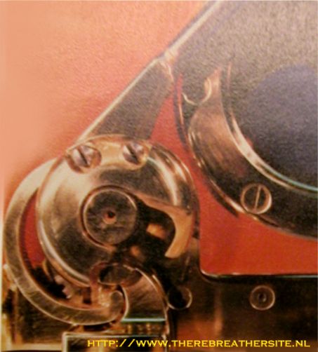
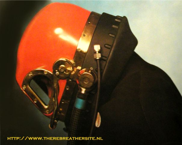
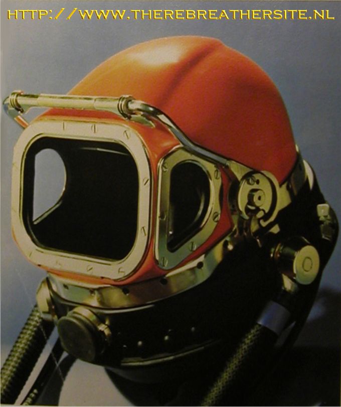
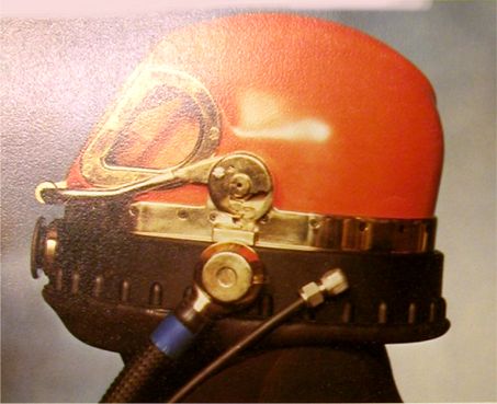
Latch Mechanism
In the pictures the ARAWAK V helmet latch mechanism is shown in both the open upper, and closed lower, positions. A single motion of the locking bar will lock the helmet in place. Five distinct actions are required to remove the helmet from the diver, indicative of the safety inspired redundancy built into Arawak V.

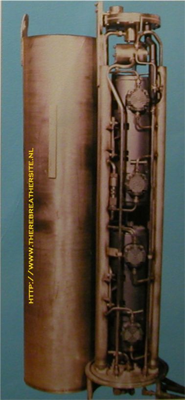
Backpack
The backpack, upper left, includes the exhaust gas accumulator, the emergency bottles, ans a gas heat exchanger. The accumulator acts as a buffer between the return pump and the helmet exhaust system, acting to dampen the exhaust gas flow. The emergency bottles are off-the-shelf components adapted to the Arawak V. A gas heater is included in the system.
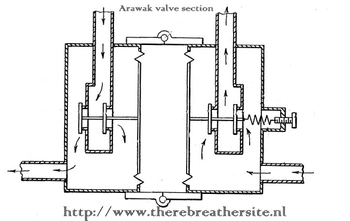
ARAWAK HOSE – FED APPARATUS
Source: Westinghouse Man -In-the-Sea Live support equipment
When using exotic atmospheres , the Arawak closed -circuit , hose-fed breathing system is a valuable auxiliary . Flexible hoses supply under water chamber atmosphere to an outside diver and return his exhalations for CO2 removal and O2 replenishment . Thus , the breathing circuit remains closed , oxygen is fully utilized , and the inert is conserved . Two Arawak systems have been used on 210 foot / 10 – day and 425 foot / 3 -day dives . Respiratory effort contributes greatly to a diver’s exhaustion . As divers descend deeper on the continental shelf , denser gas mixtures are encountered which demand every consideration co solve respiratory effort problems . Breathing effort must be minimized for maximum diver efficiency . The system contains a hydrostatically and mechanically coupled valve which is physically similar in appearance to a conventional , demand regulator . It is located near the center of the diver’s chest . Breathing bags act as a flexible volume tank in that one bag maintains a quantity of gas at ambient pressure for easy inhalation. The other bag provides a collector for ambient -pressure , easy exhalation.
To overcome pressure variations that occur as the diver moves about , both up – stream and down – stream valves in each chamber are provided so that the varying pressure or vacuum tends to hold one valve closed as it much as it tends to force the other valve open . When thus equalized , the line or conduit pressure variation no longer affects the pressure required across the valve diaphragm to open or close the valve . Also , two valve openings help the dense gas flow in the chamber of the coupled problem .
The respective Arawak valves close before the diver has consumed or exhaled to the full capacity of the bags . Although this is essentially a demand system , the breathing bags remove the peaks of breathing effort that are always present in demand valves under increased gas density conditions . This equipment is unique in that the system design eliminates many problems created by dense gas mixtures , is highly stable positionally , and it stays calibrated during rough handling.
Over the last few years work has gone into improving commercial bail-out capability in the North Sea. These efforts have been motivated in part by the Norwegian Petroleum Directorate (NPD) regulations and the recognized need to improve the working divers gear, specifically helmets and bailout systems.
Two projects were funded to develop diving gear that would meet the NPD regulations for capability to 400-500 msw/1302-1628 fsw range. One group, led by British Petroleum Norway (BP), focused on the Arawak 5, developed by Reimers Engineering, as a starting point. Building on the development efforts of Mr. W. J. O’Neill, BP set out to meet the NPD requirements.
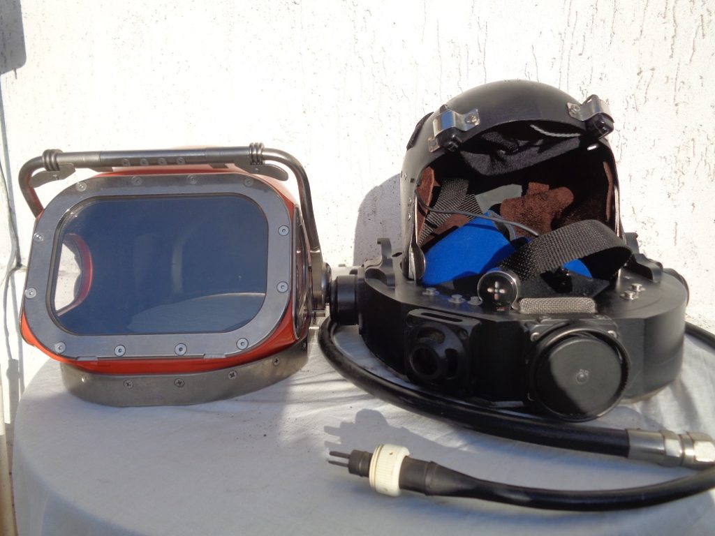
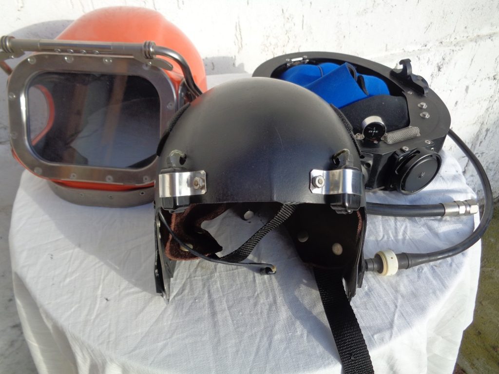
To develop a bailout system that would support a diver for a minimum of 10 minutes at 500 msw/1628 fsw, O’Neill began with a simple concept—the canister in a hat—a stainless steel CO2 canister designed to fit inside the helmet shell with a fold away mouthpiece.
If a diver’s primary gas supply is interrupted using this device, the diver goes on bailout by moving the mouth piece into place and re-breathing the gas in the hat. This is accomplished by operating a lever located on the outside of the helmet. Check valves in the mouth piece and canister insure that the gas is passed thru the canister for CO2 removal. The helmets neck dam provides the necessary compliant valve to act as a counterlung and diver-carried gas bottles supply metabolic and volume make-up gas. The prototype canister in the hat was first tested at Reimers in 1991 by Mr. Melvin Kvamme, a Norwegian diver on loan for the project. After swim testing the rig with promising results and further engineering work, Reimers was able to confirm the viability of this innovative design. Testing showed an added benefit of the rig was the exothermic reaction of the absorbent material and CO2. While on bailout, a substantial amount of heat is generated in the canister, enough to be felt through the helmet shell—a real plus when diving in cold water. At last report, Reimers called the system, Dolphin Seven, and was looking for further field test opportunities.
Source: Aquacorps Journal 23
Report by Office of Naval Research March 8, 1967
ARAWAK SYSTEM ON SEALAB
B. Deleman, B. Cannon, W. T. Jenkins, and P. A. Wells
U. S. Navy Mine Defense Laboratory
Panama City, Florida
INTRODUCTION
The Arawak system for divers was purchased on contract from Westinghouse Electric
Corporation of Baltimore, Maryland. Equipment delivered consisted of four motors, four
pumps, and two sets of breathing-gas hoses (100 ft each), with vests and demand regulators.
At Long Beach Naval Shipyard, the equipment was dismantled and installed on a common
base above the entry hatch. Minor modifications were made prior to installation. Gate values
were procured and installed in the supply and return systems to cross-connect all units, so
that one set of hoses would always be ready for use.
After completion of installation all units were checked out and tested. Results were sat-
isfactory, but the units were very noisy. The time element prevented elimination of some of
the noise problems common to these pumps and compressors. Space limitations also restrict-
ed the installation design.
ARAWAK EVALUATION, TEAM 1
General
No specific record of Arawak time was kept while Team 1 was in Sealab, except in the
ship’s log. Therefore, only an estimate of the time used can be made at this time. Of the to-
tal period spent outside the habitat, divers employed the Arawak system about 50 percent of
the time. Since the major portion of Team I’s initial tasks concerned the habitat or immedi-
ate vicinity, the Arawak was used considerably the first nine days. It is ideally suited to this
situation.
Advantages and Disadvantages
The major advantages of the Arawak are (a) lack of predive preparation, and (b) unlimited
gas duration. The units were very reliable, with the only malfunction being a stuck vane on
No. 2 vacuum pump. This pump was repaired on the bottom satisfactorily.
The hoses were a nuisance, getting tangled and twisted every couple of days. The vest de-
sign needs improvement, especially in the way the hoses attach. There is a tendency due to
the weight of the hoses to pull the vest open. The regulator is too close under the chin and
must be disconnected to get out of the vest. The range was about 80 ft horizontal and 30 ft
up or down. At times kinks developed, causing extremely hard inhalation or exhalation.
Operation
The Arawaks were used extensively for pot handling, PTC work, and removal of the outer
port covers. They were easy to breathe in, and, since the two vacuum and two pressure pumps
ARAWAK SYSTEM 95
were paralleled, supplied plenty of gas. The vests were awkward to get into, and a tender
was definitely needed.
Recommendations
Smaller, neutrally buoyant (or slightly negative) hoses would be helpful, and the vest needs
some redesign. The regulator should not be so close under the chin, since ditching the rig
would be virtually impossible. The pumps were very noisy and need some sort of acoustical
shielding inside the Sealab.
ARAWAK EVALUATION, TEAM 2
General
During the 13 diving days that the members of Team 2 were in Sealab 11, the two Arawaks
were used a total of 36 hours, or slightly more than 1/3 of the total diving time of some 98
hours 50 minutes. Individual use of the rigs varied widely from man to man, with ranges of
5 to 70 percent of total diving time being Arawak. Every aquanaut used these rigs from a low
of 18 minutes total to 10 hours 14 minutes total, with an average use of 3 hours 36 minutes
per man.
Initially the Arawaks were used as a secondary or ‘iDack-up” system to the Mark VI, but
more and more emphasis was placed on them each day. Most Arawak dives were very local,
being used for pot transfer and general maintenance work on or in immediate vicinity of the
habitat. No Arawak dives were made to distances greater than 50 ft. from the habitat due to
hose limitation.
Advantages and Disadvantages
Advantages of the Arawak included the ease and rapidity with which it could be made ready
for use. The unlimited gas supply and the safety of being tethered to the habitat gave the aqua-
nauts an additional feeling of security which was not felt using the Mark VI. The time and ef-
fort necessary for setting up a Mark VI for a dive was an additional strain on the aquanauts;
the Arawak was a welcome relief from this.
Disadvantages were incurred using the two Arawaks, the most prominent of which was the
noise inside the diving- staging area while the pumps were running. This noise, plus the dis-
torted voices, made conversation nearly impossible in this area. In addition, the buoyant hose
had a tendency to pull the aquanaut up and back as he swam out from the habitat. This hose
tended to kink and also tended to snag on the transfer pots, which made it unsafe to use during
pot transfer. The limited range in which a diver using the Arawak could operate was the most
important factor governing their use.
Recommendations
Improvements should include a baffle system so the pumps could be run and not interfere
with conversation. Hoses should be neutrally buoyant so they won’t kink; and a safe, quick-
release system should be incorporated into the harness. The quick release is necessary due
to the chance that a diver, in an emergency, would have his hose snag while swimming back to
the habitat.
ARAWAK EVALUATION, TEAM 3
General
Use of the Arawak varied from at least one dive for all members to 12 dives for one
member. Team average was three dives. The Arawak was used a total of 84 hours.

Therebreathersite was founded by Jan Willem Bech in 1999. After a diving career of many years, he decided to start technical diving in 1999. He immediately noticed that at that time there was almost no website that contained the history of closed breathing systems. The start for the website led to a huge collection that offered about 1,300 pages of information until 2019. In 2019, a fresh start was made with the website now freely available online for everyone. Therebreathersite is a source of information for divers, researchers, technicians and students. I hope you enjoy browsing the content!