
1913 Dräger Dänische Tauchretter D2
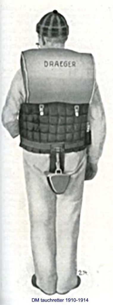
| Manufacturer | Dräger made this rebreather for submarine escapes in 1913-1914 especially for the Danish Navy. |
| Gassystem | This rebreather runs on oxygen only and uses a constant mass flow system addidng 1,25 ltr/min. |
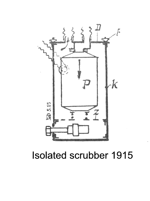
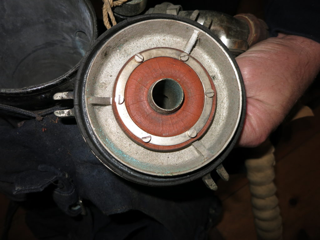
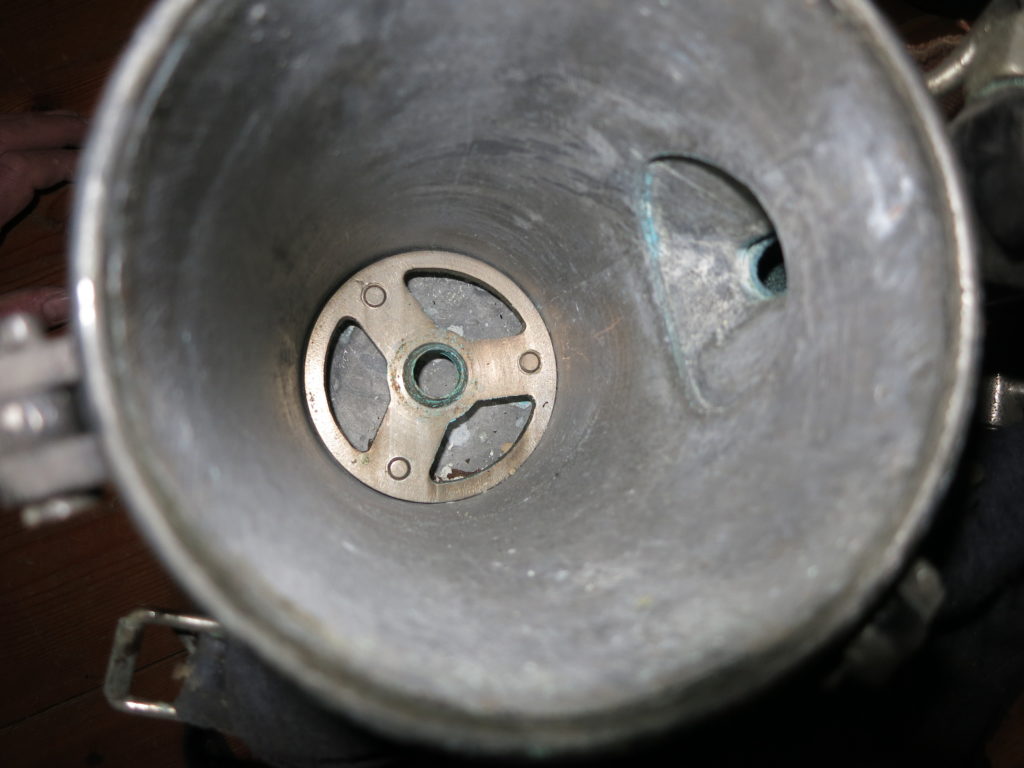
| Scrubber | The unique scrubber is placed in an insulated container so that the cold seawater cannot affect the function of the absorbent material. |
| Buoyancy | The rebreather is equipped with an additional floating device on the chest to control the ascent and improve bouyancy on the surface. |
| Characteristics | The device is equipped with 1 hose to the counter lung, so the rebreather is a pendulum rebreather. |
| Mouthpiece | The breathing hoses ran to a mouthpiece with mushroomvalves and a shutt-off valve |
IMPORTANT NOTICE:To the readers of this page: Not all information about this rebreather is known. If you have any information about this rebreather, please send it to me. I can then add the information and make it available to all interested readers. Your contribution is crucial! Please send your addition to jw.bech@quicknet.nl
The oxygen rebreather is equipped with a seperate lifejacket and a float. The diver can drop the breathing apparatus when reaching the surface.
The diving apparatus was developed in 1913 or 1914 and has great similarities with the DM1 and DM2.
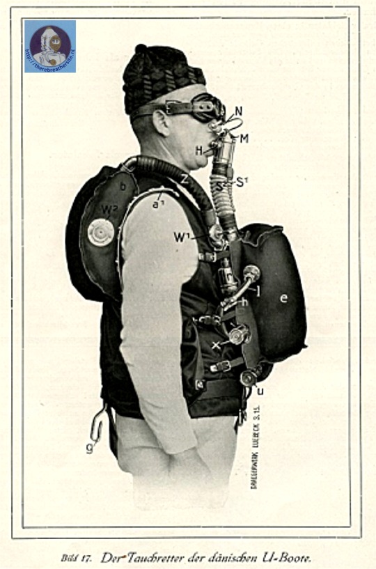
H: The model Denmark T2 was developed in 1913 and appeared in 1916 in catalogues
V1:Discharge valve through which the carbonated gas was discharged to the scrubber
V2: Inlet valve, prevents the gas from flowing back and feeds the diver with oxygen rich gas.
N: Nose clamp, allows the diver to breathe only through the mouth. The use of the nose clip is still common today in full face masks.
M:Mouthpiece, valve housing and valve. The purpose of the valve was sometimes to close the breath loop so that no water can enter if the mouthpiece is not in the mouth. Sometimes a surface positioning is also provided in which the rotary valve opens to the outside air and the diver can breathe with the mouthpiece in at the surface without having to remove the mouthpiece.
S1:Inlet hose, the corrugated hose carries the gas to the diver with a rich oxygen mixture. The inlet hose forms a connection with the counter lung worn on the back.
S2: Exhaust hose, the corrugated exhaust hose carries the CO2 gas to the scrubber.
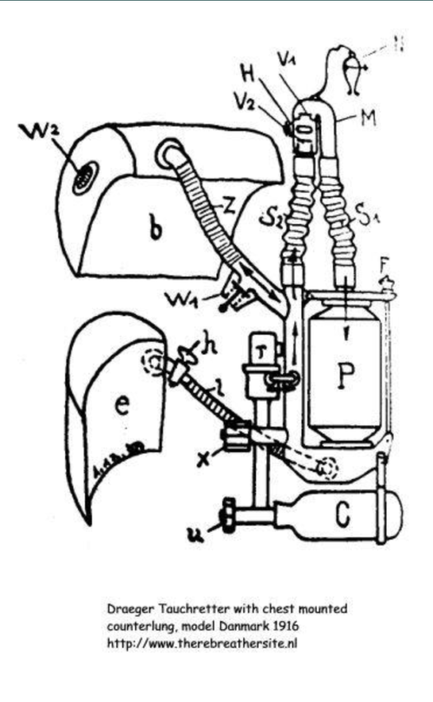
P: The scrubber, filled with CO2 absorbing chemicals often consisting of sodium or potassium hydroxide, absorb the CO2 and feed the low-oxygen gas to the inlet side of the breathing apparatus. This specific scrubber had an inner housing that prevented direct contact with the seawater.
C: Oxygen cylinder, the cylinders were often only filled to 120 bar in those years. The 0.8 litre (?) bottle provided a dive time of 1 hour at a flow of 1.25 litres per minute. Whether that time was needed for an escape depended on the circumstances.
U: Tap, the tap fed the gas under high pressure to the reducer which reduced the pressure to 9 bar.
X: The Bypass valve. If a larger amount of gas was desired in the circuit, the diver could allow gas from a high pressure in the circuit. This increased the constant mass flow of 1.25 l/min.
T: Constant mass valve, reduces the 9 bar oxygen pressure to an even gas flow of 1.25 ltr/min. This amount was calculated assuming a reasonably relaxed person breathing. Whether this was reasonably calm during an escape is doubtful
E: Swimming bladder, to regulate the ascent speed or as a swimming aid on the surface
B: The counterlung performs the function of catching the exhaled gases.
W1: Overpressure valve, if the diver has too much gas during the ascent, e.g. by using his bypass valve, or by the expansion of the gas during the ascent, the gas can be blown out by the operating the valve. The valves were often adjustable and also functioned as a pushbutton bleed.
Z: Pendulum hose, the connection between the diving apparatus and the counterlung. The gas oscillates between the lung and the inlet side of the device.
W2: Pendulum hose, the connection between the diving apparatus and the counterlung. The gas oscillates between the lung and the inlet side of the device.
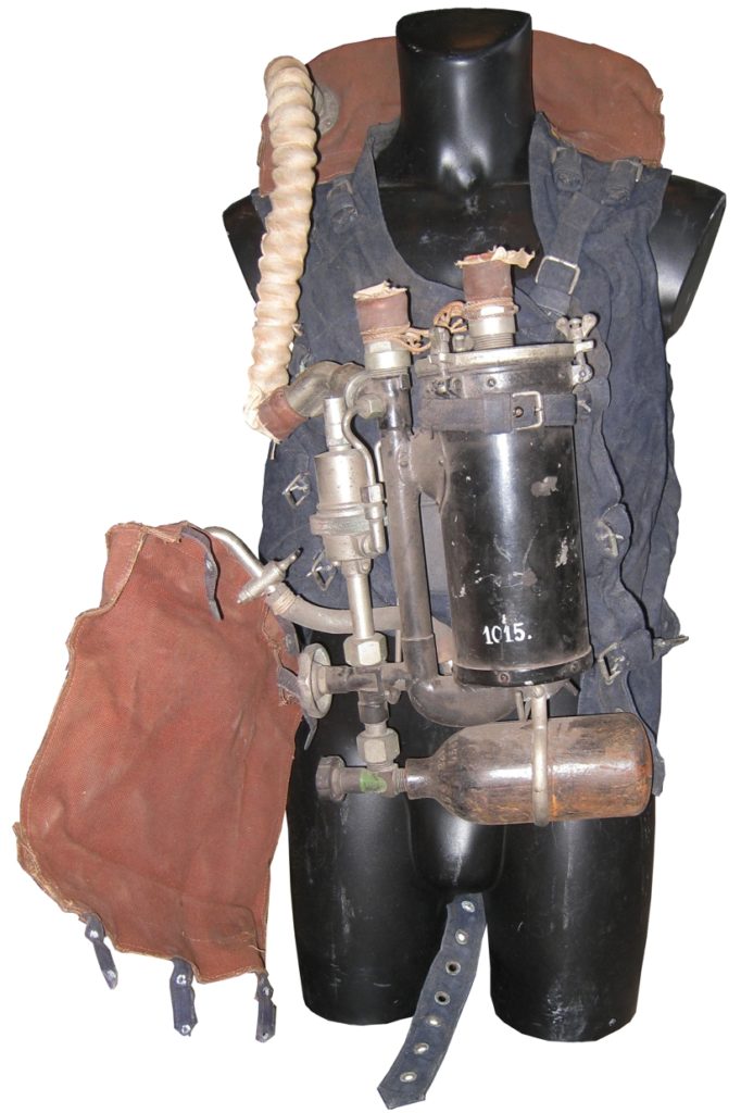
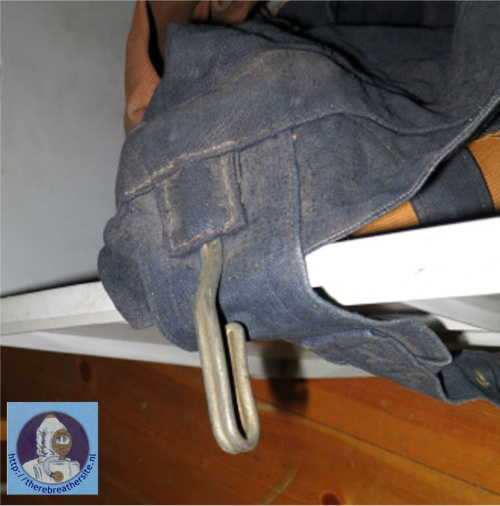
On the right hand side picture you see a hook that was part of the divers harness. On the hook was attached a weight of 4 or 5 kg (?) with which the sailor who wanted to escape from the submarine initially stayed below. As soon as he threw away the lead block, the ascent started. With the swim bladder he was also able to influence the ascent speed.

Therebreathersite was founded by Jan Willem Bech in 1999. After a diving career of many years, he decided to start technical diving in 1999. He immediately noticed that at that time there was almost no website that contained the history of closed breathing systems. The start for the website led to a huge collection that offered about 1,300 pages of information until 2019. In 2019, a fresh start was made with the website now freely available online for everyone. Therebreathersite is a source of information for divers, researchers, technicians and students. I hope you enjoy browsing the content!