

In 1904, the retired technical chief of the Regia Marina, produced a very interesting drawing of an armoured diving suit. His specification described two models that both showed an excellent knowledge of the problems and proposed viable, though sometimes very complicated, solutions.
The following article was written by Faustolo Rambelli, president of The Historical Diving Society Italia 1994-2020. It is my pleasure that Faustolo and HDSI have given me permission to translate the original article from the revue HDS NOTIZIE n. 42 of may 2008 and make it available to the readers of my website. The article not only describes the construction of Restucci’s design, but also shows a picture from the past. I would like to thank Faustolo for his contribution!
The Restucci patent can be found here: https://worldwide.espacenet.com/patent/search/family/032487497/publication/GB190619771A?q=pn%3DGB190619771A

In 1904, the retired technical chief of the Regia Marina, produced a very interesting drawing of an armoured diving suit. His specification described two models that both showed an excellent knowledge of the problems and proposed viable, though sometimes very complicated, solutions.
There were several Italians who in the late 1800s, early 1900s were involved in that wonderful period dedicated to research and technology to the study and realisation of diving systems. Unfortunately, apart from a few articles in magazines or newspapers of that time, there are almost no Italian publications describing the diving equipment of these inventors. It is in fact from the book by Pesce’s book, La navigation sous-marine, of 1906, where we we learn of their names and findings.
– Toselli: in 1871 with the “Talpa marina” and in 1884 with the “Neptune”.
– Balsamello: in 1889 with the ‘Palla nautica’;
– Pietro Degli Abbati: in 1892 with the ‘Audace’ a working submarine for divers;
– Corzetto-Vignot: in 1896 with the “Sphere metydric sphere” 1)
– Piatti dal Pozzo: in 1897 with the “Lavoratore submarine;
– Giuseppe Pino: in 1903 with the “Battellosubmarine worker” and in 1904 the “Hydroscope”. 2)
It should be noted, however, that all the machines listed above were related to diving equipment such as spheres or turrets. There has not been an Italian who dedicated himself to different systems like Giuseppe Restucci, in 1904. What little was generally known about Restucci was this:
From: R. H. Davis, Deep diving and submarine operations, St Catherine 1935.
1 – An extensive report on the “methydric sphere” of Gorzetto-Vignot appeared on “HDS Notizie” n° 9 – June 1998.
2 – A report on Giuseppe Pino’s inventions appeared in “HDS Notizie” n° 15 – April 2000.
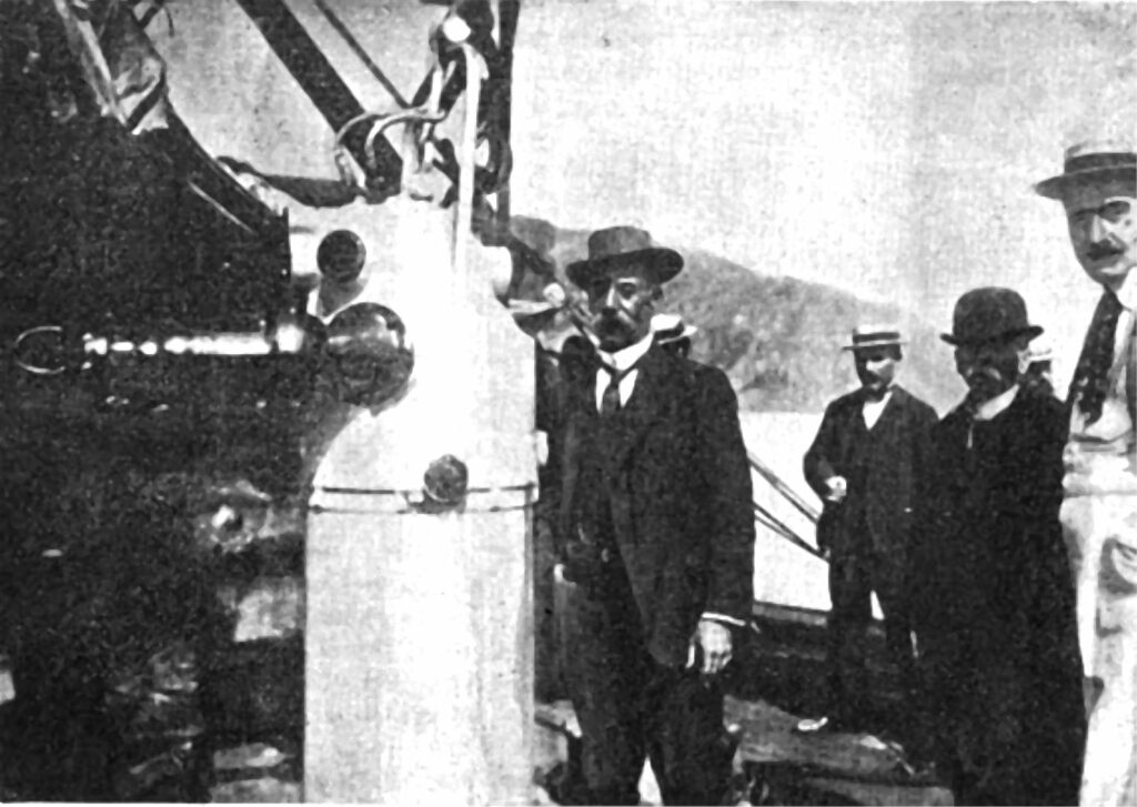
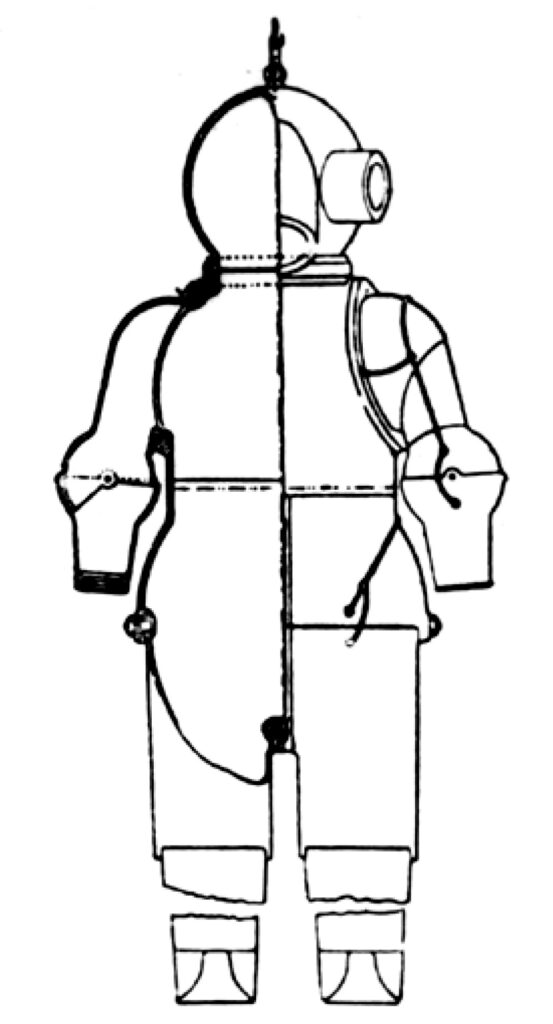
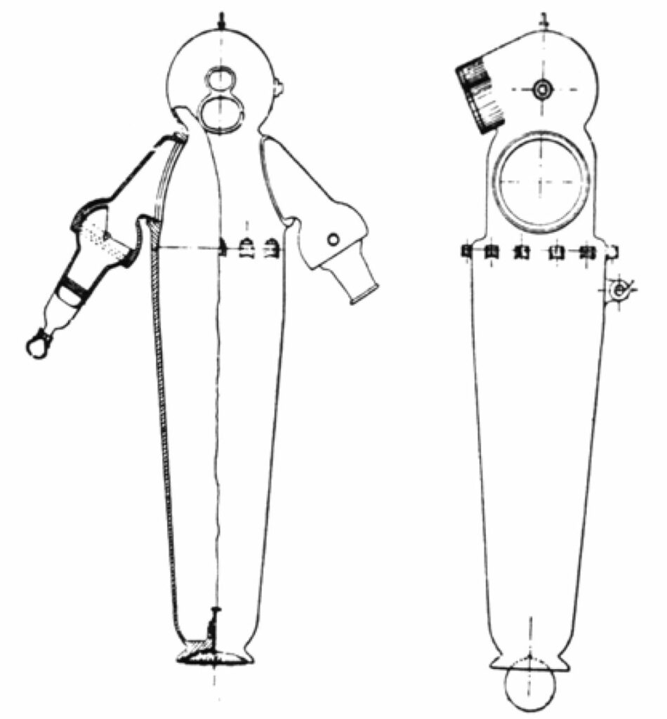
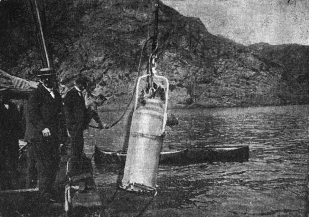
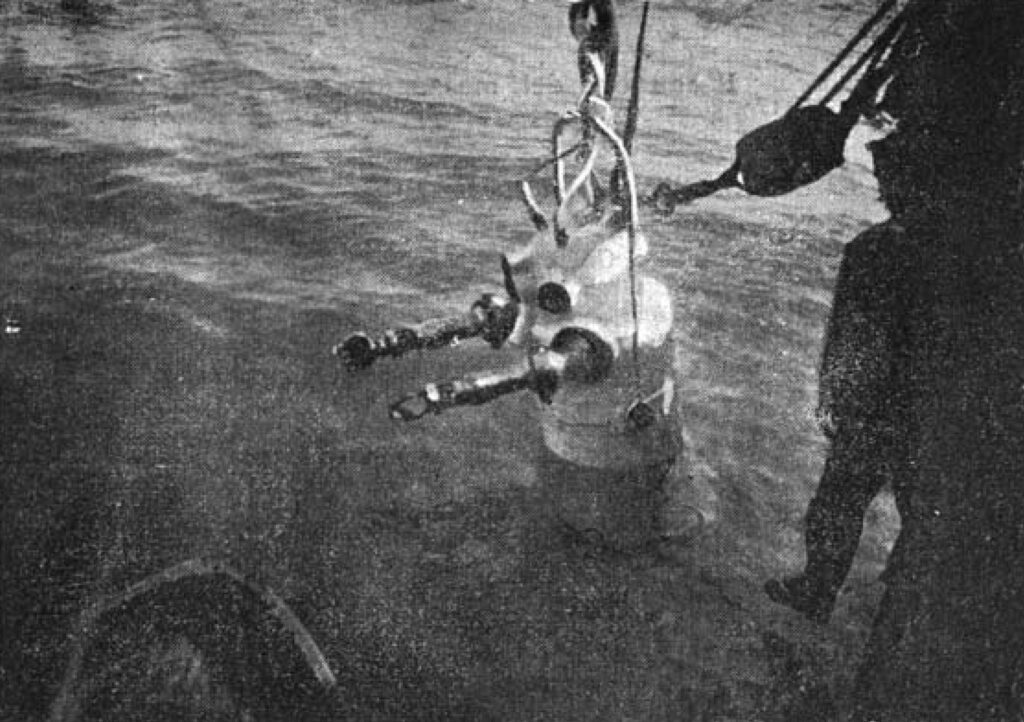
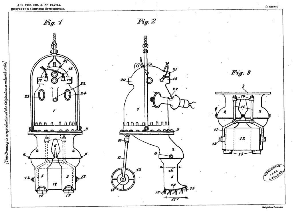
In 1904, Giuseppe Restucci from Naples made a very interesting drawing of an armoured diving suit. In his specifications, he described two models of diving suits, both of which demonstrated an excellent knowledge of the problems and proposed practicable solutions, even if they were sometimes very complicated. (Figs. 1 and 2) Restucci proposed holding the joints of his diving suit together and rotating them using compressed air at a pressure slightly higher than the external pressure, so that the air prevented water from entering. Nevertheless, the inside of the suit remained under atmospheric pressure. The overpressure to the joints was sent through small tubes by means of a suitable compressed air supply, not from the suit itself. This was feasible in theory, but in practice there were difficulties such as controlling the pressure at the joints, keeping the pressure constant as the joints moved or stopped, and preventing air leakage, not to mention the fact that the diver would have to carry either spare air or two supply hoses, one for air at atmospheric pressure for the suit and one at higher pressure for the joints. Restucci’s first model shows a complete armoured diving suit with articulated arms and legs (eight joints in total). The second model is a very simple one with only articulated arms and no other movement. The lower part is a simple cone containing the diver’s legs. The diving suit is designed to hang from a cable attached to the back, slightly above the centre of gravity. At the bottom of the cone is a small inflatable bag which, when inflated, makes the suit rotate from the vertical to the horizontal position. In this way, the diver maintains a certain degree of control over his movements when on the bottom. The small balloon is inflated by a small pump operated by the diver with his feet. From: “La tribuna illustrata”, n° 30 – 29 July 1906. The new Restucci diving suit for great depths. Since ancient times, human ingenuity has been devoted to the search for tools to explore the depths of the sea. In this field, modern technology has made it possible to make considerable progress. The photos we are presenting were taken last Monday 250 metres off the coast of Portofino, during experiments with the new metal diving suit invented by the retired chief engineer of the Royal Navy, Giuseppe Restucci, a Neapolitan. Restucci’s diving suit is made of iron and is more than a centimetre thick.
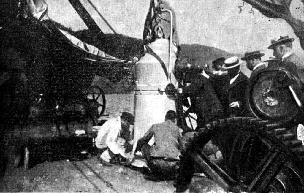
It is large enough for a man to stand upright and gives him relative freedom of movement; it is cylindrical and narrows at the top to form an approximate sphere. This part is fitted with cristal windows all around to enable the diver to explore the bottom of the sea. The most ingenious part of the device consists of two bronze arms, similar to two human arms. The forearm is articulated, the right hand has the true shape of a man’s hand, the fingers have the same movements. In the left arm, the actual hand has been replaced by a pair of pliers and scissors. The inside of the diving suit is equipped with an electric light with which the diver can explore the seabed in the dark.The diver communicates with the escort vessel by means of a telephone and a well-designed breathing system, so that the man can stay underwater for a long time in optimal conditions. Last Monday’s experiment is not the first, as the same diver, Mr. Trama, has already descended to the bottom of the Black Sea with the Restucci device and found a ship wanted by the Russian government, sunk near Balaclava during the Crimean campaign, with a precious cargo of 45 million in gold. The experiments in the Black Sea will be renewed, as the Russian Government studies the means of recovering the precious cargo that has been lying at the bottom of the sea for more than 50 years. The work of the intelligent Italian technical chief seems destined to have a great future. Confirmation that Restucci’s ADS has worked in the Black Sea also comes from an article on behalf of Alexander Sledkov, president of HDS Russia, and Nyle Monday, of HDS-USA.
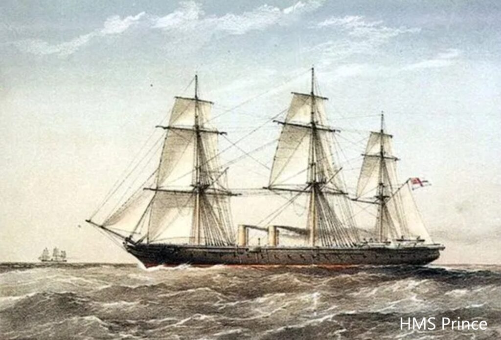
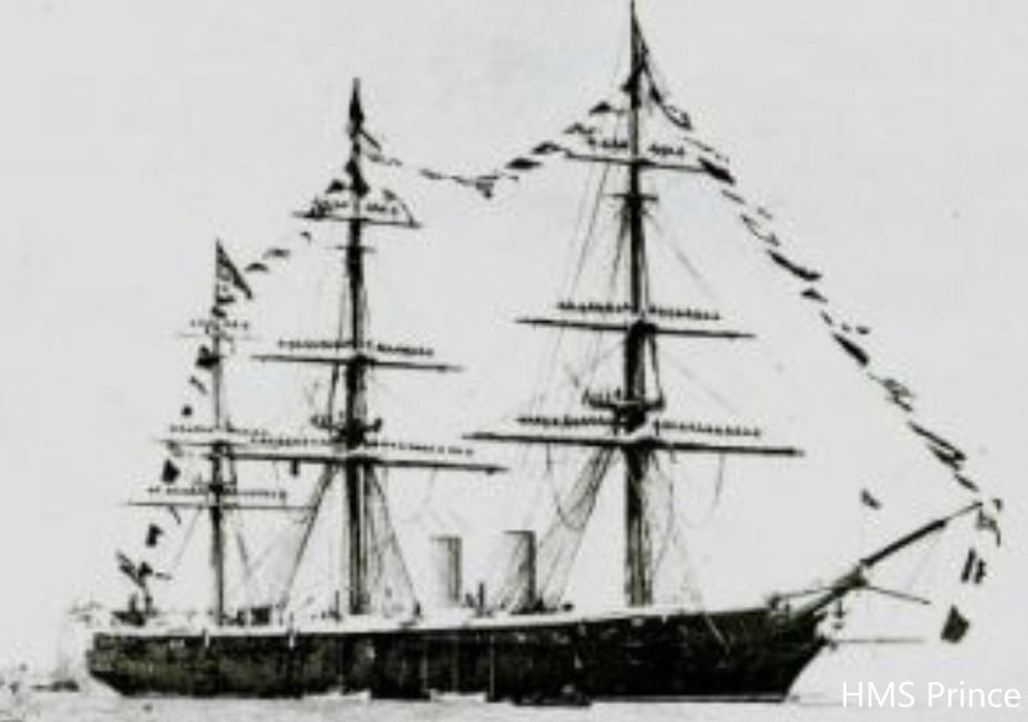
However, it is necessary to make a small premise now. In 1854, the Crimean War broke out between the Ottoman Empire, France and Englandagainst Russia which, after an 11-month siege, lost the city of Sebastopol on the Black Sea. 15 km from Sebastopol lies the city of Balaklava, on the bay of the same name, which the British had occupied and made their naval base, while the French had established themselves in the bay of Kamishovy. The “Prince” was a steamship that had left the Thames on 14 October 1854 with on board, in addition to the normal cargo of provisions for the war, the officers and men of the 46th regiment, as well as the troops’ pay estimated at between 200,000 and 500,000 pounds. On 8 November the “Prince” arrived in Balaklava, landed the 46th Regiment, but not the cargo, and anchored outside the bay in 50 feet of water along with many other ships. On 1 and 2 November, the area was hit by a tremendous hurricane, with the epicentre at Balaklava, which caused the destruction of shore camps and the loss of about 60 ships and 1500 men. Among the sunken ships was the “Prince”, which was thrown against the rocky coast and smashed to pieces. Of the 150 crew members, only one cadet and six sailors were saved.
From: “The History of Russian Diving”, no. 2 – 2003.
Excerpt from the article “Secret of the Japanese mask” by Nyle Monday and Alexander Sledkov where they talkabout the Crimean war of the “Prince”
“… Immediately, while everyone was trying to forget the senseless victims of the stupid war, there were several people who boasted about the whereabouts of most of the cargo of the “Prince”, which was the salary for the expeditionary corps and whose value ranged from £200,000 to £500,000, depending on the period. Many people tried to recover the gold of the “Prince”. In particular, the French made an unsuccessful attempt in 1875, then another expedition in 1896, and later an Italian company. But in those days the diving and research equipment were not so perfect as to enable the ambitious project to be brought to a successful conclusion. As for the Italian company’s attempt, some Russian sources and other information say that in 1901-1903 they used the equipment invented by their compatriot Giuseppe Restucci.
Robert Davis states in his book that this type of equipment appeared at the end of 1904, and the president of The Historical Diving Society Italy, Faustolo Rambelli, also informs us that it was certainly used in diving operations in the Black Sea, but in 1905. This fact is confirmed by the photographs concerning these events, on the back of which is written “1905”. The photographs were taken by Yu. K. Pavlovsky, an experienced diver and excellent instructor, son of K. A. Pavlovsky. …
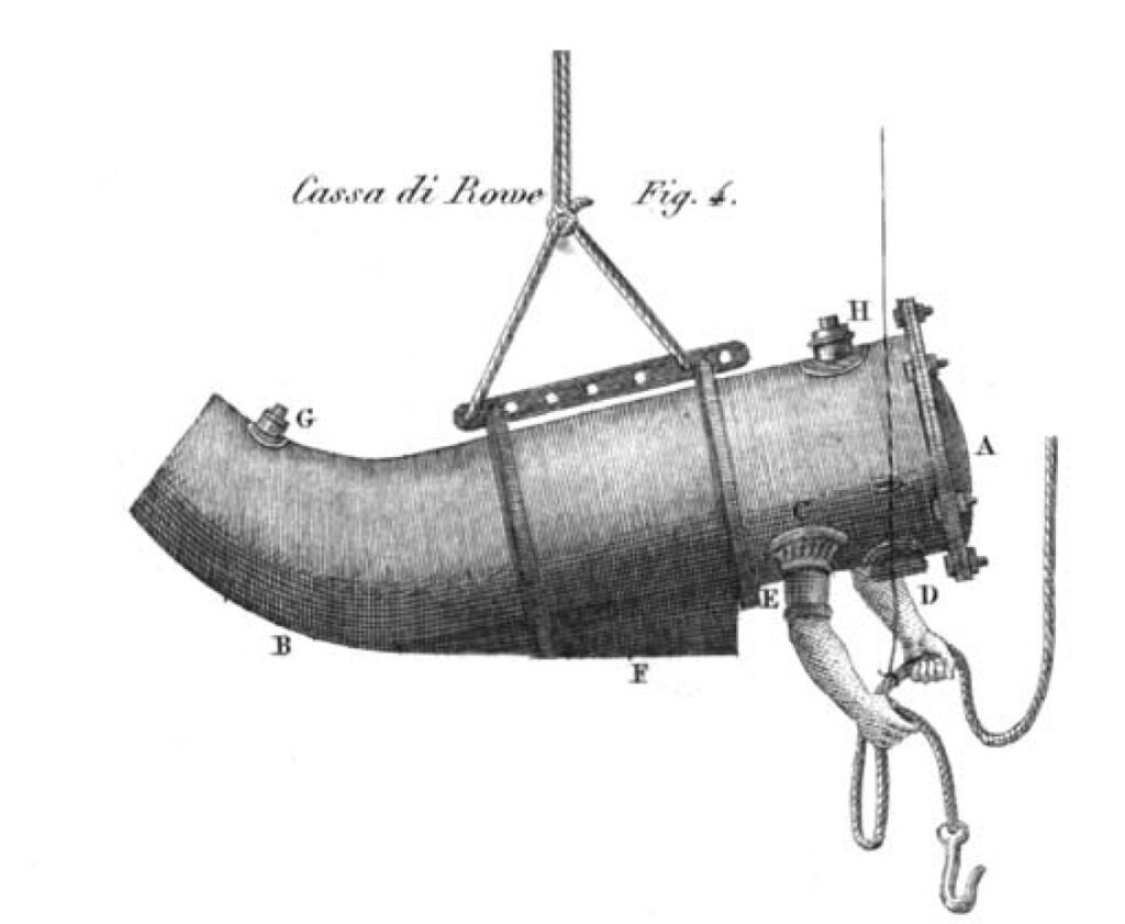
” From the above we have three ADS of Restucci: – that with legs and arms of 1904 (fig.1), which we shall call model “A”; – that with cylindrical body and only arms of 1904 , which we shall call model “B”; – that with cylindrical body and only arms of 1906 , which we shall call model “C”. In 1904, after the project of the ADS model “A”, a traditional concept with legs and arms, Restucci chose a simplified solution when designing the model “B”: a cylindrical body and only two arms. What makes the model “B” most surprising is the fact that Restucci went back in time almost 200 years with this solution. He went back to the concept of the first ADS in history, which was not really an ADS, namely the “Lethbridge – Rowe type vessel” of 1715(Fig 7) , i.e. a wooden vessel with the culvert closed inside and with protruding arms, thus the body subjected to atmospheric pressure and the arms to ambient pressure. In reality, however, this is a good solution because the diver can work standing up, if necessary, but also lying down in case he needs to, for example, poach objects on the bottom.
This was undoubtedly more difficult, if not impossible, with the traditional ADS with legs and arms, model “A”. There are also structural differences between the same models “B” of 1904 and “C” of 1906. The “B” model has a rather slender oval hull, with a single porthole at the front and a headlamp above it. The “C” model has a much larger cylindrical body than the previous one, with a porthole at the front and a headlamp above it, but in addition it has two side lights and one at the rear.
The remainder of this page describes Restucci’s patents.
I, GIUSEPPE RESTUCCI, Mechanician, of 156 Corso Garibaldi, Naples, Italy, do hereby declare the nature of this invention and in what manner the same is to be performed, to be particularly described and ascertained in and by the following statement :-
This invention relates to improvements in diving and dredging apparatus and has particular reference to a cuirassed diving chamber for great depths which is provided with a toothed instrument for picking up pearls, corals, sunken objects or the like from the bottom of the sea.
In the accompanying drawings-
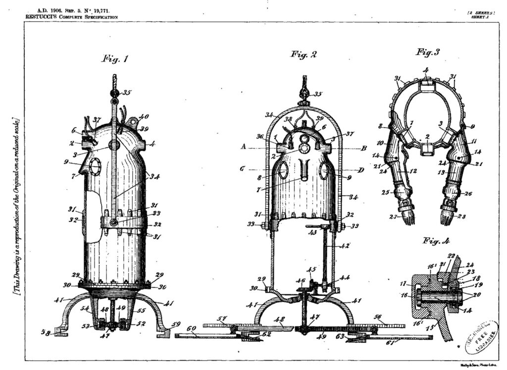
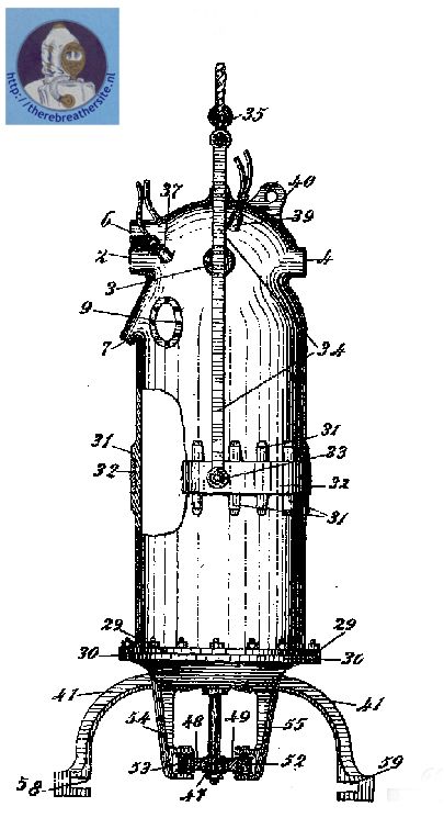
Figure 1 represents a side view of a device embodying the invention,
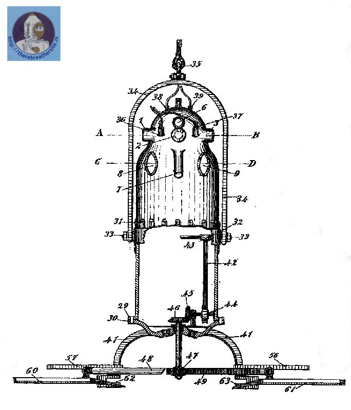
Figure 2 is a perspective view, partly sectional, showing the rake-operating device,
Figure 3 is a section on lines A–13 and C-D of Figure 2.
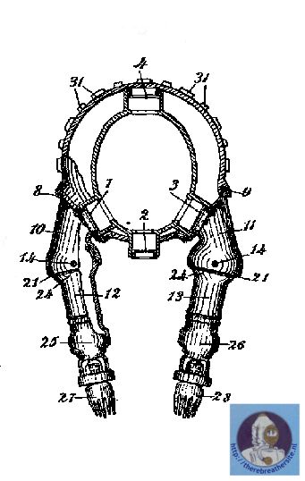
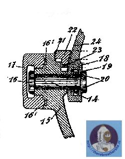
Figure 4 is a detail on an enlarged scale of an elbow joint.
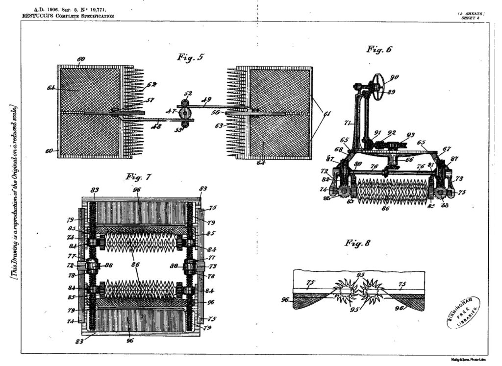
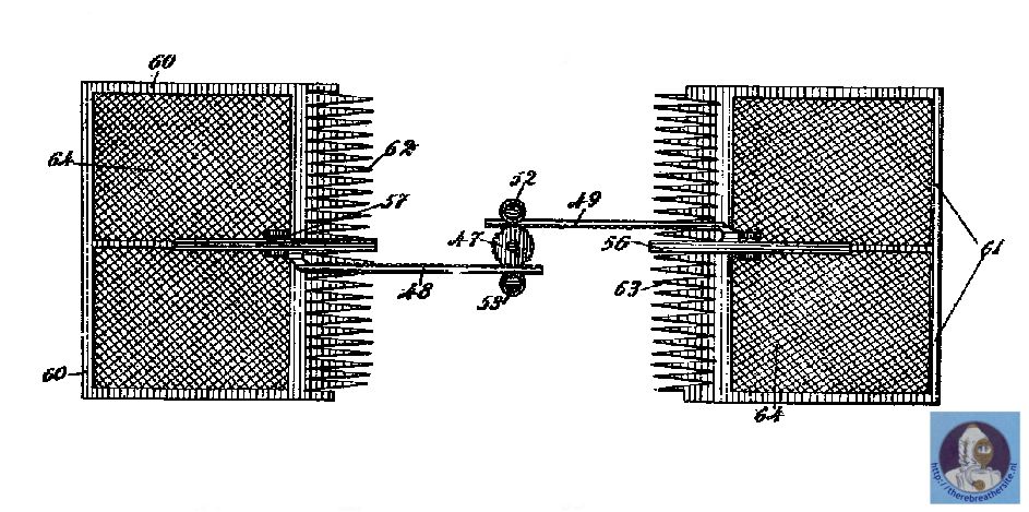
Figure 5 is a plan view of one construction of the rakes,
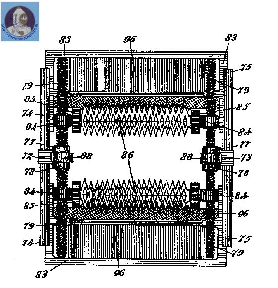
Figures 6, 7 and 8 are respectively an elevation, a plan and a detail of a modified form of the rakes. –
The said cuirassed diving chamber is made of bronze, or other metal considered to be conveniently resistant and light and fit as far as concerns the hydrostatic pressure due to the depth in which the cuirassed chamber is submerged and as far as concerns the working that it must accomplish being under water. As will be seen from Figures 1 and 2, at the top where -the head of the diver is enclosed there are provided five port holes 1,2, 3,4 and 6, four of which, namely 1, 2, 3 and 4 are to enable the diver to see through, and are arranged as shown, one in front, two at the sides and the fourth behind, directly opposite to that in front. All four port holes have their central line in the same horizontal plane. The other port hole 6 is smaller than those marked 1,2, 3,4, and is placed, as shown in Figures 1 and 2 above the port hole 2 ; it is somewhat spherical as it is intended to serve as a light reflector ; if light be required, it is provided by means of an electric lamp which is placed in the cuirassed chamber at the top in a position corresponding to the above described port hole G.
The appendix 7, Figures 1 and 2, is a tube in which another port hole is contained, also for sight and adapted, in consequence of its obliquity, to allow the diver to observe from a vertical position objects lying on the bottom at a very little distance from the diving chamber.
Arranged one on each side of the said tube 7 and at the same distance from it, are two holes 8,9. To these holes which end in suitable surfaces to receive them, are attached the shoulders 10,11, secured. thereto by screws at a suitable angle of inclination.
To the above mentioned shoulders the two arms 12, 13, (Figure 3), are fitted, so as to be movable on the elbow on pivot 14 (see Figure 4).
Figure 4 represents a section of one elbow on a plane passing through the pivot 14; both elbows being identical in construction, one description applies to both. The arm at the elbow terminates in a bull which is exactly lifted
into the interior of the shoulder which latter terminates in a spherical cavity to receive it. DiumetricaHy opposite and corresponding to the articulation of the different elbows the two pivots of rotation are fixed. Each pivot 14 is rigidly fixed in its bearing 15, tightened externally by a nut 16 (see Figure 4). The said bearing 15 is provided all around with a groove capable of containing a washer 161 inserted therein, and forming a joint which is made tight by the screw cap 17 screwed on to the extreme end of bearing 15 and arranged so as to press on the said washer, to obtain a perfectly tight closure. 18 is a lug on the outermost end of the ball which, as has been mentioned forms the elbow and through which passes pivot 14 and around which the arm rotates.
The above mentioned lug is provided withe circular cavity 19 in which is fitted and secured an annular box containing balls 20 to reduce friction, when rotating by rolling instead of sliding.
The shoulder in proximity to the elbow at 21 is screw-threaded (Figures 3 and 4) in 21 where the circular stuffing box 22 (shown in section in Figure 4) is screwed.
By thus screwing on the said stuffing box the packing 23 which is in the cavity is compressed and forms a close joint all round the ball 24 which forms part of the arm 12 or 13.
To the extremity of the arms two chambers 25 and 26 arc screwed, adapted to freely contain the hands of the diver and in which devices are fixed which are adapted to open and close two artificial hands, as 27, 28, to open, ~shut and hold instruments requisite for the work that is required to be done.
On the said cuirassed chamber studs 31 are provided so as to leave all around a space to receivea steel belt 32. This belt is formed by two half rings carrying two projecting studs 33 on which a fork 34 is mounted.
The, fork is fixed at 33 by two nuts, as shown and it is provided at the top with a pivoted eye 35 through which passes the cable that supports the cuirassed chamber.
On the head of the chamber two sockets 3G and 37 are provided in which two tubes are fixed through which the rising and descending current of air for the respiration of the diver is established, which respiration is quite as natural as in the open air.
Two further sockets 38 39 are provided to which, if required two conduct- ing cables for light are fixed. 40, Figure 1, -is an appendix on the head con- sisting of a big eyelet in which a large hook is engaged and on which a second cable is secured forming a second support for the chamber. By means of the belt 32 and the fork 34, if desired, the whole of the apparatus may be rotated around the pivots 33 ‘ by means of a rope fixed. at the base and pulled from the surface from which the diving chamber is operated and’ guided. The studs 31 serve to hold the belt 32 in place in whatever position the chamber is placed.
As before mentioned the chamber may comprise a flange 29 to be secured to the base 30 by means of bolts. and nuts. The said base comprises four ribs 41 which are adapted to support the rakes.
On the disc; forming the base 30, at 90 to each other, four port holes are provided, of which three will serve for the diver to see through and the fourth to project the light furnished by a lamp placed behind it.
The object of these port holes is to allow the diver when in his vertical position to observe the objects on the bottom of the sea, and to. be able to pick them up by means of the rakes.
The said rakes are operated in the following mariner:-
In the first form, shown in Figures 1 and 2, there is an axlo 42 moved by lover 43 which by means of an endless screw rotates wheel 44 and thereby the wheel gear 45, 46and 47.
48, 49 arc two racks fixed respectively to the frames 60 and 61 which owing
to the rotation of 47 receivc .a movement of translation towards and away from each other at will according to operation of lever 43.
52, 53 (Figure 5) are two rolls fiied to standards 54, 55, Figure 1 which rolls have the object to guide and establish the continuous contact of racks 48, ‘ 49 with wheel 47.
56, 57 Figure .2 are appendices of the two racks which in the translation of the frames slide in guides provided in the ribs 41 in -order to prevent lateral displacements of the, frames in their movements. The frames GO and 61 terminate in rakes G2 and 63 (Figure 5) the shape of the teeth being indicated in Figures 2 and 5.
The said frames GO and 61 arc closed by a wire gauze G4 and also the frame formed by the ribs 41 is closed all around by wire gauze.
The apparatus and diving chamber as described have the following objects.
1st. The possibility of approaching the bottom of the sea in order to inspect its’ nature and the objects lying on it.
2nd. The possibility of standing on the said bottom to pick up objects- that may lie found there, which by means of the enclosure of the frames will remain contained in the ribs 41 and in the wire ,gauzes G4.
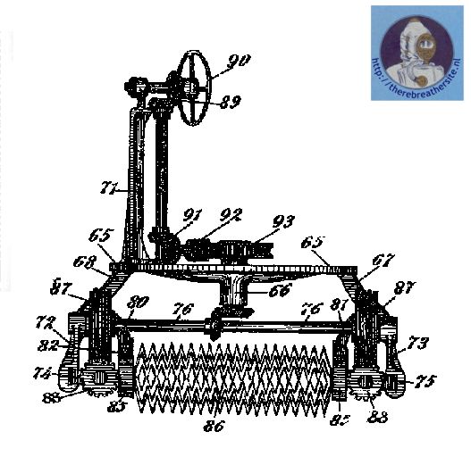
The modified form shown in Figures Ii,. 7 and 8 comprises:- –
lst. A metal disc (i5 (Figure U) on which the .cnirassed chamber is fitted, the said disc having a bearing 66 and four symmetrically distributed ribs on its circumference two of which 67 and 68 are shown..
2nd. A standard 7.1 (Figure 6) rigidly .secured to the said disc.
3rd. Two supports 72 and 73 (see Figures 6 and 7) fixed directly -opposite and in the centre of the lateral ribs 74 75 (it must be noted that the four ribs from the disc 65 lead, two by two, to join the extremities of the ribs 74, 75 (Figure 7). The said supports present three bearings each, one of which embraces the axle 76 (see Figure 6) and the other two 77 and 78 (see Figure 7.) embrace the screw 79.
. 4th. Two ribs 80, 81 fixetl to the four ribs of the disc and parallel to the ribs 74 and 75 (see Figure 6). To each of those ribs and for their whole length a rack 82′ is fixed.
5th. Two frames 83 (Figures 6 and 7) adapted to slide in the ribs ?:4,,T5 (Figure 7),
6th. To each frame two nuts 84 are fixed and these arc united by means of an axle around which the four wheels 85 and the two toothed gripping instruments rotate (sec Figures 6 and 7).
7th. An axle 76 bearing a bevel wheel and two endless screws at the extremities.
8th. Two worm wheels 88 (Figures 6 and 7).
9th. The pair of bevel wheels 89 moved by the hand wheel 90 which may also be arranged so as to be rotated by an electric motor.
10th. The pair of bevel wheels 91 and the combination of tho worm 92 with its worm wheel 93..
From the above description of the apparatus it is seen that the rotation of the, four toothed wheels 85 must take place at the same time with the translation of the two frames 83 (Figure 7); in fact by rotating the hand wheel 90 rotation will be imparted to shaft 76; the latter by means of the endless screws 87, and worm wheels 88 will rotate the two lateral screws 79 (Figure 6) and these screws having no movement of translation, will oblige the nuts 84 to run their respective length, and these nuts as before said, being united by means of an axle and integral with frames 83, the translation of the axle and the frames will consequently take place. The axle having fitted on it the toothed wheels 85 it is obvious that during the translation they will -be subjected to rotation that will be communicated to the gripping instruments 86 because they are closely joined. Having in this way described the apparatus and its function, it results clearly that plants fiid molluscs on the bottom of the sea
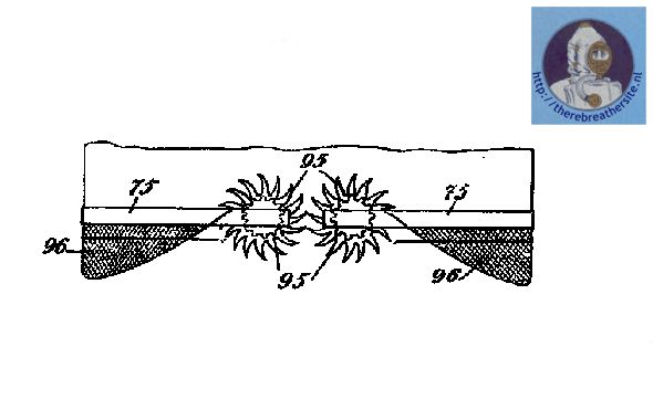
may be easily picked up. If the hand wheel is rotated in the opposite direc- tion, that is to say from right to left, the gripping- instruments 86 withdraw from each other. Thus the gripping instrument is adapted (or the picking up because by rotating the hand wheel 90 from left to right, the gripping instru- mnts tend to approach each other, and at the same time while approaching gradually they rotate on their centres. Whatever plant or mollusc may come between the teeth 95of the above mentioned gripping instruments are caught by thom and brought into the gathering nets 96 (see Figures 7 and 8).
Having now particularly described and ascertained the nature of my said invention and in what manner the same is to be performed, I declarc that what I claim is : —
1. In apparatus for diving and dredging a diving chamber composed entirely of metal suspended in a hinged support and provided with raking apparatus substantially as described.
In the same patent Restucci announces a second design. This patent envisages an ads with a mechanism to move forward.

Therebreathersite was founded by Jan Willem Bech in 1999. After a diving career of many years, he decided to start technical diving in 1999. He immediately noticed that at that time there was almost no website that contained the history of closed breathing systems. The start for the website led to a huge collection that offered about 1,300 pages of information until 2019. In 2019, a fresh start was made with the website now freely available online for everyone. Therebreathersite is a source of information for divers, researchers, technicians and students. I hope you enjoy browsing the content!